The LongRa boards are currently sold out!
Turnkey Arduino 32-bit LoRa solution
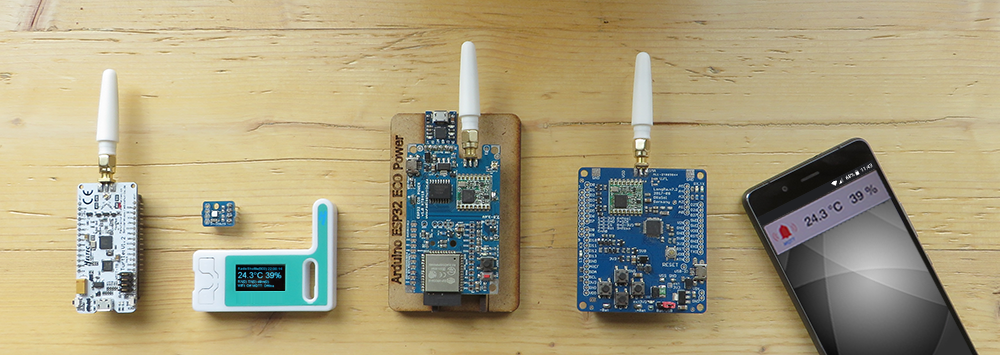
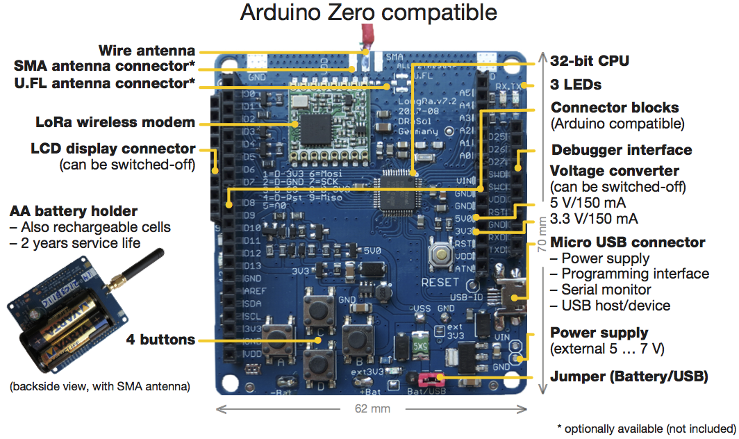
The turnkey LongRa board is Arduino Zero compatible, and can immediately be deployed in Arduino environments. The included RadioShuttle wireless protocol software allows node-to-node communication without the need of additional routers or servers. The solution is designed for battery operation (2x AA batteries) but can also be operated with an external power supply. A standard Arduino connector allows extensions that require 3.3 V or 5 V. Simply brilliant!
32-bit ARM processor with 32-bit computing power
Our LongRa board is built around a 32-bit ARM processor based microcontroller (MCU) from ATMEL. This same this ATMEL SAM D21 processor with 256 kB Flash and 32 kB RAM is also built into the Arduino Zero or Genuino Zero. The USB port connects the board to a Windows, Linux, or Mac computer. Thanks to the pre-installed Arduino bootloader, the operating system and the Arduino IDE recognize it as Arduino/Genuino Zero. Of course, it can also be used via ATMEL Studio or other programming environments such as “Mbed”.
RFM95 LoRa radio module
We use the 868/915 MHz RFM95 transceiver module from HopeRF as the LoRa radio module. It is specified for a maximum constant transmission power of +20 dBm or 100 mW, which must not exceed an effective radiated power of +14 dBm in the EU. The achievable link budget, which roughly speaking represents the quality of the entire radio link with all losses and gains, is stated by the manufacturer as 168 dB. The LoRa chip built into the RFM95 module is based on the Semtech SX1276 development.
The essential signal lines of the RFM95 module are directly connected to the ATMEL SAM D21. This enables our RadioShuttle software to control the module’s full range of functions. And there are no hardware restrictions on the development and testing of other radio protocols that stand in the way of your own creativity and willingness to experiment.
A simple wire, which is soldered and tuned to the board itself, is sufficient as an antenna. If you want to install preassembled antennas, you will also find soldering pads for SMA and U.FL plugs on top of the board.
Flexible power supply
We have tried to design the power supply of the circuit as modularly as possible. During programming, the board can be completely powered by USB. A simple voltage transformer then keeps the entire circuit board ready for operation at 3.3 volts. If you want to use an external power supply, you will find a separate input for a supply voltage between 5 and 7 volts on the board. This input uses the same controller as the USB port.
On the back of the board, a compartment for 2 AA cells is firmly mounted. Regular or rechargeable batteries can be used here. Since the processor and radio module operate stably and without performance loss in a voltage range between 2.1 and 3.5 volts, no voltage regulator is connected here. This is particularly energy-saving and guarantees a long operating time when powered by batteries. If you want to use other external batteries, you will of course find a corresponding connection.
You can choose between battery or USB power via jumper. This prevents the regulator from “sucking” the battery backwards. The same plug contact can also be used e.g. for an on/off switch on the sensor module’s housing.
Boost converter
Various sensors and actuators require a regulated supply voltage of 3.3 volts or 5 volts for safe operation. In order to be able to supply such external auxiliary switches in spite of low battery voltages, we have provided the LongRa board with an adjustable boost converter. In normal radio and computer mode, it is switched off to save energy. It can be switched on at any time via software and can provide 3.3 volts or 5 volts on the corresponding pins. Either way, the MCU and radio module continue to receive the low battery voltage. 5 volts sensor signals may therefore only be supplied to the IO pins via a voltage divider.
Depending on the type of battery and its state of charge, the converter can maintain an output current of up to 150 mA at the selected voltage level. For current peaks, we have provided a backup capacitor with generous capacity. Electric motors and magnetic disk drives in particular can generate very high switch-on current peaks and thus cause an impermissibly large voltage drop on the entire LongRa board. In such cases, additional external power sources must be used.
IO concept
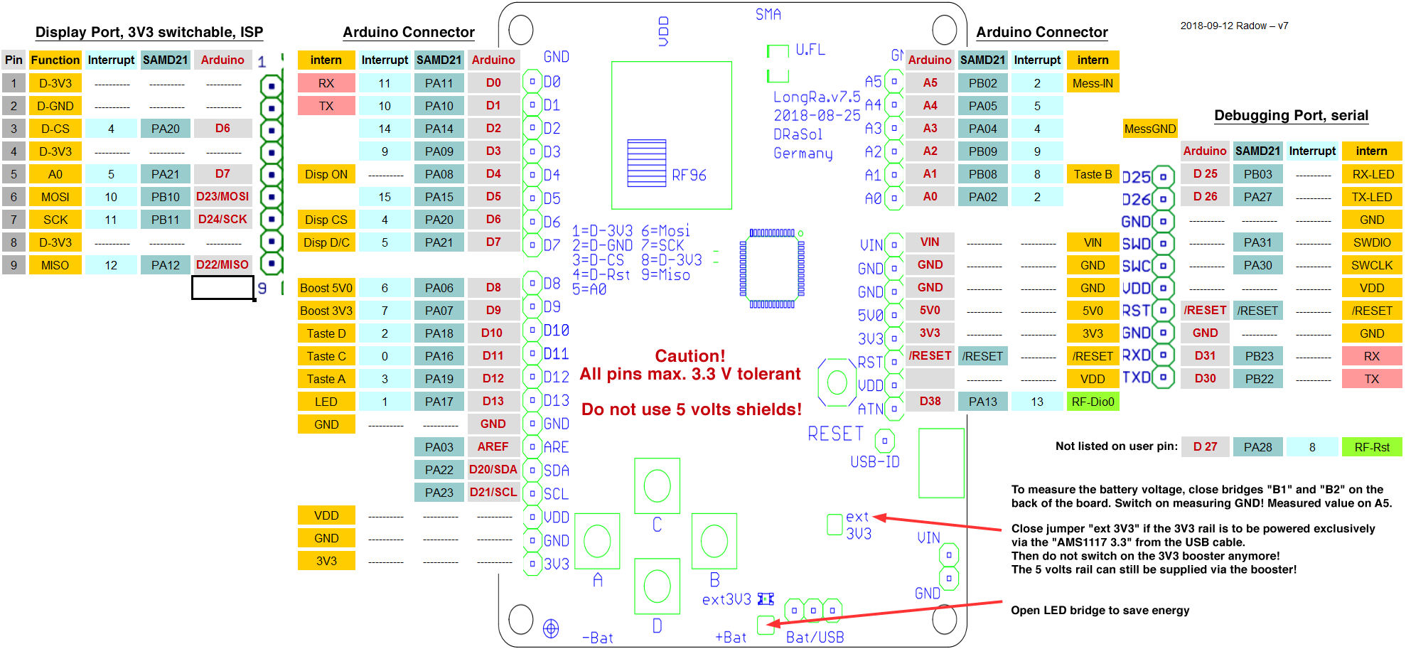
The inner two pin header rows on the LongRa board are 1:1 signal compatible with the Arduino Zero layout. Due to the extensive equipment of our board, various pins are already internally preassigned by the system. They are addressed in the source code in the same way as the Arduino Zero and can be used in some cases for your own applications – see connection diagram. For common sensor nodes, there are sufficient digital, analog, serial, I²C (Inter-Integrated Circuit) and ISP (In-System Programming) connections available.
Note:
The ATMEL SAM D21 is only voltage tolerant up to 3.3 volts and all signals above 3.3 volts have to be reduced accordingly by a voltage divider.
Pin assignment on a LongRa board with Arduino Zero bootloader (rev. 7.5 and newer)
Pin assignment on a LongRa board with Arduino Zero bootloader (rev. 7.2)
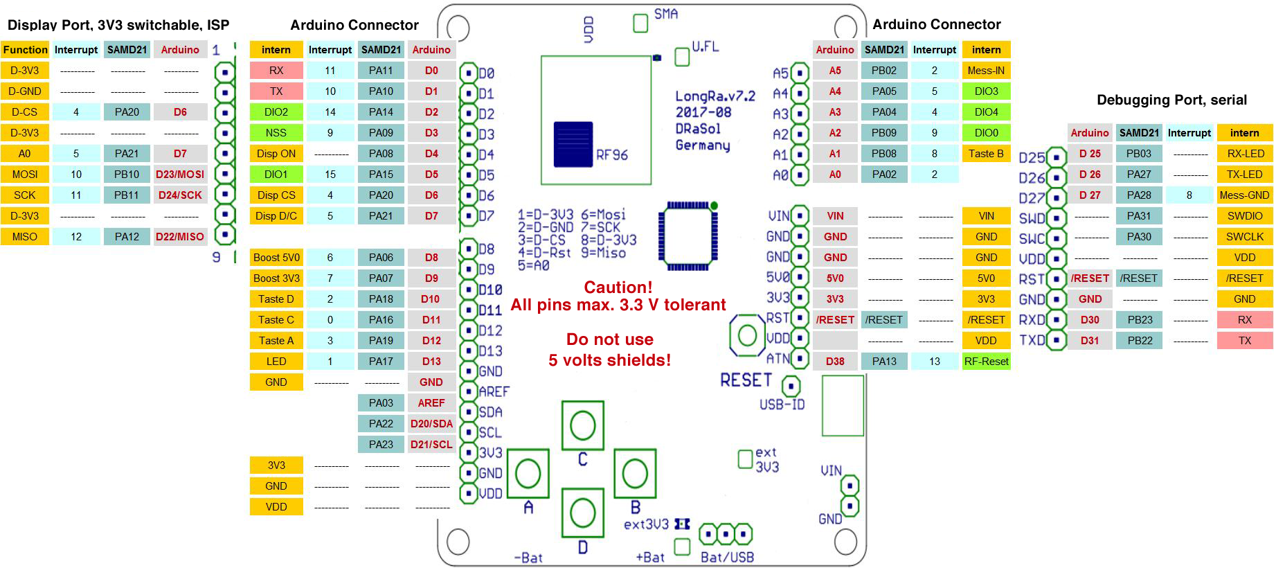
On the left side of the board – antenna pointing upwards – there is a display port or ISP slot developed by us. In addition to the usual ISP lines, there are two I/O lines and 3.3 volts connections. This means that a TFT colour display or any other ISP subscriber can be connected to the board with only one connector strip.
In battery operation, 3.3 volts are provided on the display port of the converter. Since some sensors can present large parasitic loads via their I/O lines, the GND line is also switched off via an n-channel MOSFET at this port, which completely shuts off the display port power supply.
On the right side we have provided a pin row for professional software debugging. Connections for SWDate, SWClock as well as a serial interface and the operating voltage allow the use of a single connector for easy programming and debugging.
For easy program operation without external hardware we have provided a reset button, 4 freely usable buttons and 3 LEDs. The key layout is specially designed for screen navigation. In addition to the Arduino standard LED on pin 13, the Arduino Zero provides an RX and a TX LED. These can also be used freely by the user via digital lines 25 or 26. Our RadioShuttle software uses it, for example, to display the transmission and reception information.
OLED display
See Operating the board with an OLED display.
Energy management
As mentioned above, we have designed the board to be as energy efficient as possible to achieve a long battery life. In summary, these measures include the electrically disconnectable 3.3 volts controller, the use of MOSFETs with the highest possible resistance for switching functions and a low quiescent current circuit design.
The RadioShuttle software supplied with the LongRa-Board is tuned to this hardware. By means of various energy-saving algorithms ranging from packet size optimization to automatic transmission power reduction with good transmission ratios, it is an essential component of mature energy management.
By using all sleep functions and a targeted use of the 3.3/5 volts converter for sensor programming, this LoRa Arduino solution makes it possible for anyone to set up battery-operated wireless sensors easily.
Continue with Commissioning
10.09.2017 – Rainer Radow