Power supply of the Turtle board
The Turtle board can be powered via battery (regular AAA batteries or rechargeable NiMH batteries). As a second option, it can be powered via the micro-USB port. The board automatically switches between USB and battery power supply, USB power has the preference.
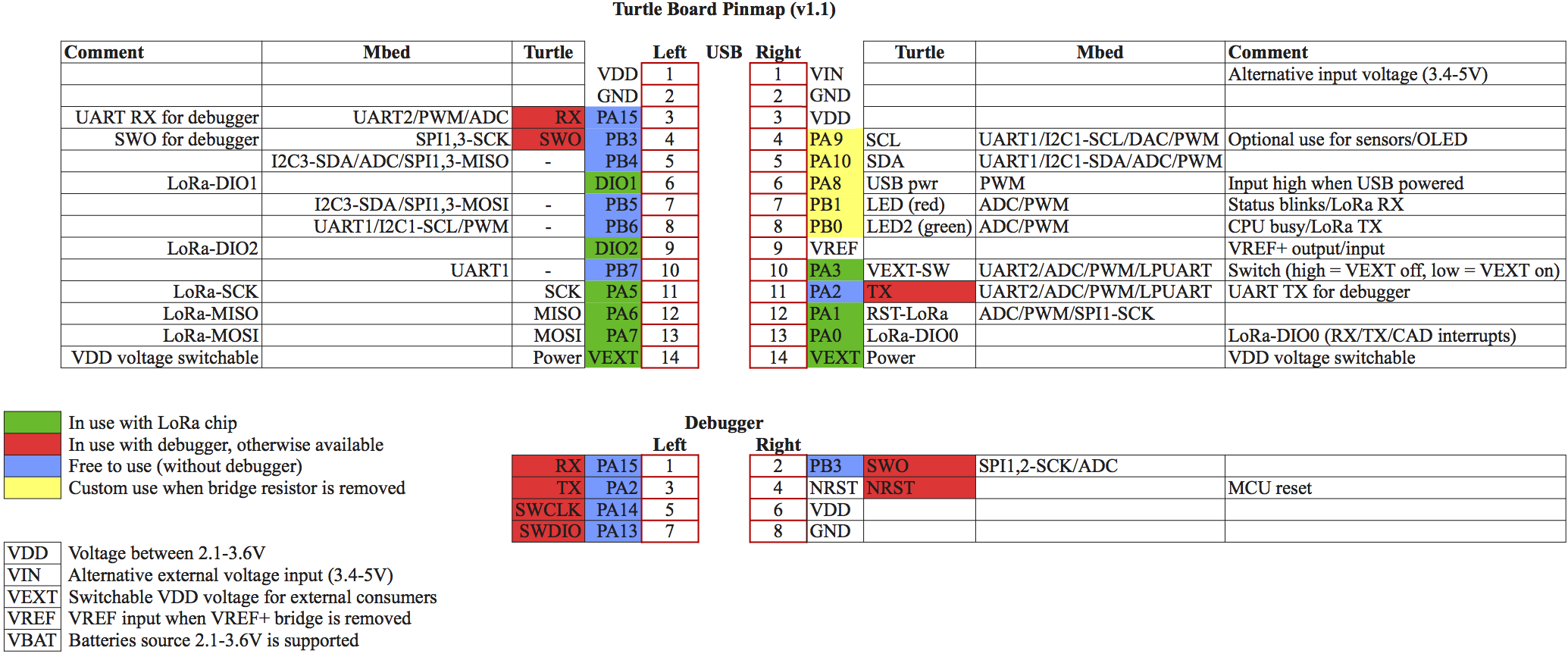
Turtle board: pin and interrupt assignment
Debugger interface
The board package includes a 2×4 pin header to be used with an external debugger. For debugger use, the header must be soldered on and connected to a remote debugger, see details on the Nucleo ST-Link Interface page. By default, the Turtle software starts and tries to connect a console to the debugger UART (TX/RX wires, 230400 baud). If no debugger UART is detected it tries to connect via a USB virtual COM port for 30 seconds. If neither of them is available there is no console output.
Note:
Low-level crash messages will only be printed on the external debugger or external UART interface because USB services will stop on crashes. All regular messages will work fine with a USB virtual COM port or with a debugger UART. Instead of a debugger UART it is also possible to connect a regular external UART to the RX/TX pins for console message printing.
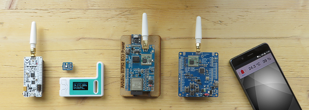
Install the antenna
There are three antenna options:
- The included SMA antenna can be connected to the SMA connector
- A U.FL connector is available for external U.FL antennas
- A basic wire can be connected, for this the SMA connector must be desoldered and the wire must be soldered to the middle pin of the SMA pad on top of the PCB
A basic wire antenna must be shortened to 8.2 cm. The antenna is adapted to λ/4 for 868.1 MHz.
The exact formula for calculating the antenna length is:Wavelength = speed of light / frequency
For λ/4 this value must be divided by 4 again.
Note:
The Turtle board is shipped adjusted for a single RF frequency (433 or 470 MHz, or 868 or 915 MHz). The frequency is marked on the board. The board frequency and antenna frequency must match, otherwise it will not work correctly.
Switch on/off voltage “VDD-SW” for external loads
An internal voltage switch allows external power consumers to be switched on and off so that they do not consume power permanently. The IO pin “EXT_POWER_SW” is defined in the file “xPinMap.h” of the RadioShuttle software for switching. It can be switched to either “EXT_POWER_ON” or “EXT_POWER_OFF”. The measurement of the battery voltage, which is measured via the “BAT_POWER_ADC” ADC pins, is attached to the “VDD-EXT” cable. To ensure that the board requires as little power as possible, the “VDD-EXT” is usually switched off.
Measuring the battery voltage
To measure the VDD supply voltage (approx. 3.3 volts when powered via USB, approx. 3.0 volts with battery operation) a measuring device is provided on the board. The battery voltage is displayed with an accuracy of about 100 mV. The voltage is measured and displayed when booting or resetting. The BatteryVoltage() function in the “RTCUtil.cpp” file measures and returns the voltage.
Turtle “deepsleep” and wake-up
The RadioShuttle sample software for the Turtle board has a main loop where it is processing tasks and goes into the Mbed sleep() function, i.e. into deepsleep for the lowest energy consumption.
Note:
When a USB console is used, sleep() cannot be called because this would disconnect the USB console. Also, deepsleep will not be entered when timer functions are registered. The MCU “LowPowerTimer” feature supports deepsleep and can be used instead.
Any registered input interrupt handler, or an RTC or “LowPowerTimer” handler, will wake up the MCU from deepsleep and continue processing immediately. After processing is completed the sleep() function will be called again and enters into deepsleep. When the MCU is in sleep or deepsleep, the green LED is turned off.
Interrupt routines design advice
By default, interrupt routines should be as short as possible and should never wait for something to avoid deadlocks. Also, printing to a USB console does not work in interrupt routines, and printing to a UART is also involved with limitations.
The Turtle board sample code has a great solution for it: The interrupt routine posts an event, the main loop picks up the interrupt event and does the processing on a user level code (non-interrupt). This allows console printing, waiting for something and easy processing:
- Add a new unique interrupt bit in the “main.h” file, e.g. MY_INT = 0x20
- In the interrupt function, send the event via InterruptMSG(MY_INT);
- In the main loop check via if (pendirqs & MY_INT) for your interrupt events
This makes programming much easier and allows dprintf() print debugging. As an example, check out how the timerUpdate() function in “main.cpp” works.
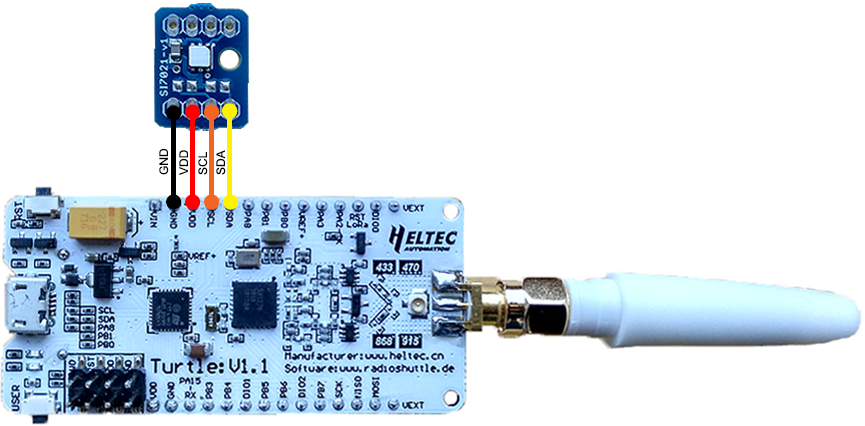
Temperature and humidity sensor (optional)
The sensor offers the possibility to measure the exact temperature and humidity in a very energy-saving way. The white felt on the sensor must not be removed, as it has a protective function so that the sensor works properly. A Silicon Labs “Si7021-A20-GM1” sensor is used, the driver is included in the RadioShuttle software.
Connect the sensor
The sensor is connected via I2C bus and requires four lines (GND, VDD, SCL, SDA). The following simple installation options are available:
- Installation at the top of the board
- Installation at the top on the back side the board
- External installation via extension cable (not included), e.g. outside the housing or directly on a heater, etc.
Please pay attention to the order of the pins (“GND” is outside); the sensor has two connection sides and can be turned so that one side fits depending on the installation (top or bottom).
Note:
Two components (optional resistors) on the sensor are intentionally not equipped, they are I2C pull-up resistors, which are already included as 10k on the main board. For an external sensor with long leads, it may be useful to solder two 1k resistors (included) to obtain stable signals. An additional option is to reduce the I2C speed. We will share our experience here later.
Software use of the sensor
If connected, the sensor is permanently active, but only requires approx. 1 μA as long as no sensor values are read. When the Turtle board is switched on (power supply on or reset), the sensor is initialized only once and the temperature is output with the start messages. When the board is started, the sensor values are automatically measured and displayed. The code for this can be found in the “Turtle_RadioShuttle/Utils/utils.cpp” file:
if (sensorSI7021->hasSensor()) {
    dprintf("%s: Rev(%d)  %.2f°C  Humidity: %.2f%%", sensorSI7021->getModelName(), sensorSI7021->getRevision(), sensorSI7021->readTemperature(), sensorSI7021->readHumidity());
}
Note:
For this, “FEATURE_SI7021” must be defined in the “xPinMap.h” file.
It is recommended not to unnecessarily read out the sensor permanently, as each readout of the values takes time and consumes power during this time. Reading out the temperature takes approx. 13 ms, that of air humidity approx. 20 ms. During this time the NUCLEOL432 MCU is active.
Battery operation
The Turtle board supports battery voltages from 2.1 V up to 3.6 V. Usually customers use 2 x AAA batteries which will provide 3 V when full or 2 rechargeable NiMH batteries which will provide 2.4 V when full. The AAA battery holder can also be swapped against a AA battery holder because its connector (wire width) is compatible.
In colder environments regular batteries and rechargeable NiMH batteries do not work well. In this case higher-quality Lithium batteries (2 x 1.5 V) can be used.
Only batteries placed in the battery holder (+/- pins) can efficiently power the board for many years in stand-by operation with regular LoRa RadioShuttle messages.
Boards powered via USB or VIN will use an LDO (low-dropout regulator) to reduce the input voltage to 3.3 V. The LDO permanently consumes a small amount of energy which would be no problem for a USB power supply but does not qualify for a long-lasting battery operation.
Note:
Rechargeable Li-ion (lithium-ion) or LiPo (lithium polymer) batteries cannot be used to power the board via the battery input pins because their voltage is higher than 3.6 V, which will destroy the MCU and LoRa chips on the board. However, powering the board by Li-ion or LiPo batteries via VIN will work.
The Turtle board has no built-in battery charger because the boards last for many years and swapping batteries is done quickly.