This document describes how to use a Nucleo STM32L476RG board to connect to a target STM MCU for firmware downloading, debugging and serial terminal connection. The Nucleo board is connected via USB to a host (Mac, Windows, or Linux), the debugging and serial wires are connected to the target. As a result, the firmware files (e.g. the Mbed “.bin” files) can be copied to the Nucleo USB drive, which the Nucleo board will then flash into the target. “Tera Term” or similar can be used as a Virtual COM terminal.
Nucleo board prerequisites
- Recommended STM manuals: UM1724, User manual, STM32 Nucleo boards
- Ensure that the Nucleo ST-Link firmware version is V2J29M18 or higher (otherwise the STML433 MCU does not work correctly):
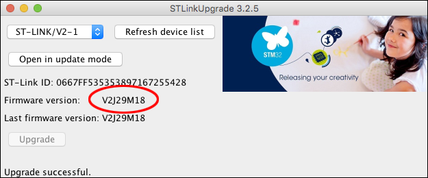
- Use the “STLinkUpgrade” utility for updating the Nucleo L4 ST-Link firmware
Preparation of Nucleo board for remote target connection
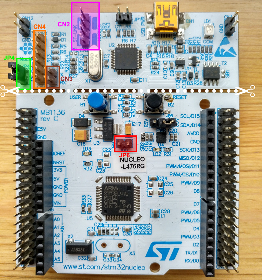
Use a standard Nucleo board which includes an ST-Link interface. Do the following to connect the Nucleo board to the target (see figure of Nucleo board below):
- Open JP6 jumper (3.3 V power of the Nucleo MCU, to avoid MCU signals)
- Solder in JP4 pin header (not factory fitted)
- Short JP4 via jumper (enables RX/TX signals on CN3)
- Open CN2 jumpers (2 x, this enables ST-Link for remote application debugging)
Preparation and connection of the adapter cable
An 8-pin adapter cable acts as an ST-Link cable and is required to connect the Nucleo board to the target:
| Signal | ST-Link Pin | Target Pin | Comment |
|---|---|---|---|
| Console | CN3-1 (RX) | J3-3 (PA15 TX) | USB Virtual COM terminal |
| Console | CN3-2 (TX) | J3-1 (PA2 RX) | USB Virtual COM terminal |
| VDD | CN4-1 | J3-6 (DO NOT CONNECT) | Debug connector, VDD is not needed and may result in reverse current, therefore leave it open |
| SWCLK | CN4-2 | J3-5 (PA14) | Debug connector |
| GND | CN4-3 | J3-8 | Debug connector |
| SWDIO | CN4-4 | J3-7 | Debug connector |
| RST | CN4-5 | J3-4 | Debug connector |
| SWO | CN4-6 | J3-3 | Debug connector |
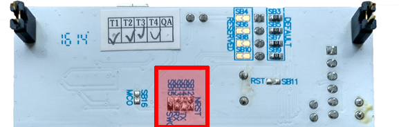
Using the RX/TX/RST/SWO lines between a remote target and the Nucleo board ST-Link interface requires desoldering the 0 Ω bridges on the underside of the Nucleo board (see figure below). Another option is to break off the ST-Link part (see white dotted line in the Nucleo board figure above).
| 0 Ω | Signal |
|---|---|
| SB12 | RST |
| SB13 | RX |
| SB14 | TX |
| SB15 | SWO |
When the ST-Link cable is connected to the target application, continue as follows:
- Connect the USB port to the ST-Link interface
The ST-Link LD1 should light up, and the USB drive “NODE_L476RG” is mounted on the desktop.
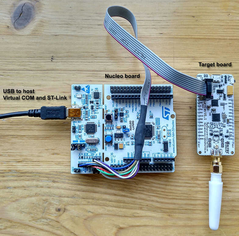
Completed setup
After all modifications have been done to the Nucleo board, according to the instructions above, the target board can be connected via the 8-pin adapter cable:
Load firmware to target
Drag and drop the “.bin” file containing the firmware to the Nucleo USB drive (“NODE_L476RG”):
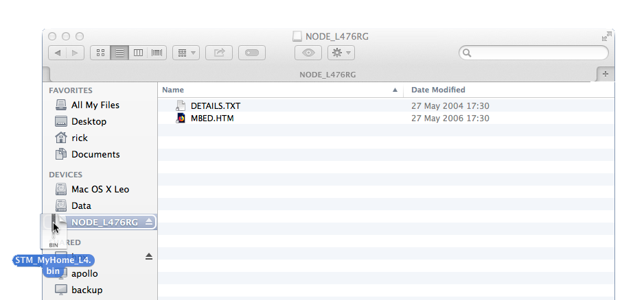
LD1 quickly flashes for a few seconds and switches to green (connected). If LD1 is lit red, no target connection could be established.
Connect target serial UART to host terminal
To allow serial print debugging, the target serial wires (CN3, PA2+PA15) are connected to the ST-Link debugger. This serial communication is forwarded to the host by the ST-Link debugger via a USB Virtual COM connection and can be used with a terminal program.
Two parameters are required to use the Virtual COM connection on the host:
- USB device name
- Baud rate
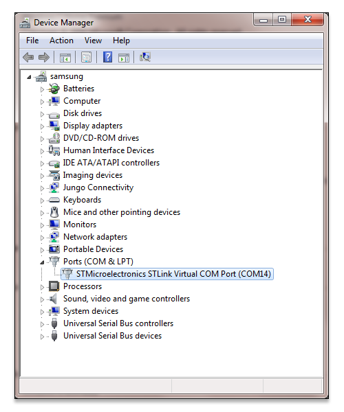
Windows
The correct USB modem COM port can be determined in the Windows “Control Panel” > “Device Manager” from the “Ports (COM & LPT)” entry:
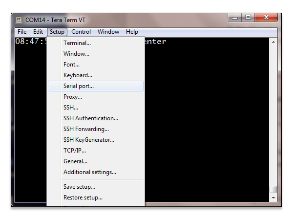
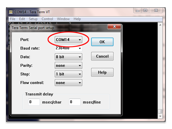
Once you have found out the serial port number, open “Tera Term” and specifiy the port number and Baud rate via “Setup” > “Serial port…”:
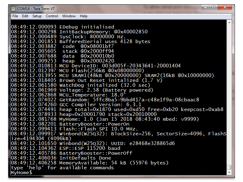
“Tera Term” sample application output (Windows):
Mac
The correct USB device name can be determined by entering the command ls /dev/tty.usbmodem* in a shell.
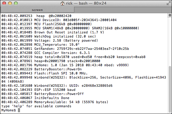
Terminal sample application output (Mac/Linux), e.g.: screen /dev/tty.usbmodemfa413 230400