Gibt es für eine Sensor (LongRange Board im LowPower Betrieb) zu RaspBerryPi & LoRa Modul als Feststation mit Internetanbindung eine Demo Installation ?
Bzw. lässt sich diese Kombi mit der RadioShuttle SW kompilieren ?
Danke für das Feedback. Aktuell gibt es kein Beispiel für eine Anbindung zum PI. Ein Bekannter hat mal eine I2C Kommunikation zum PI entwickelt, ist aber im Lieferumfang nicht dabei.
Muss also selber programmiert werden.
PS: Langfristig wollten wir MQTT per WiFi und/oder Ethernet unterstützen. Sobald es fertig ist wird es hier dokumentiert.
Hallo, habe am Wochenende endlich die Zeit gefunden und mich mit den Boards beschäftigt. Mit der Doku kommt man sehr gut zurecht. Danke an die Macher 🙂
Das Hochladen ist erfolgreich, bis zu dem Zeitpunkt, wo der Fehler erscheint, dass das Board an dem COM, der eben noch funktionierte, nicht mehr verfügbar ist.
…also es ist so, dass ich nun auch die Software auf die Board geladen bekomme. Wenn ich nun den Seriellen Monitor 3 sec nach Aufspielen des Sketches öffne, kommt folgende Meldung:
processing.app.SerialException: Fehler beim Öffnen des seriellen Ports „COM28“.
at processing.app.Serial.(Serial.java:147)
at processing.app.Serial.(Serial.java:82)
at processing.app.SerialMonitor$4.(SerialMonitor.java:101)
at processing.app.SerialMonitor.open(SerialMonitor.java:101)
at processing.app.AbstractMonitor.resume(AbstractMonitor.java:104)
at processing.app.Editor.resumeOrCloseSerialMonitor(Editor.java:2218)
at processing.app.Editor.access$2200(Editor.java:79)
at processing.app.Editor$DefaultExportHandler.run(Editor.java:2196)
at java.lang.Thread.run(Thread.java:748)
Caused by: jssc.SerialPortException: Port name – COM28; Method name – openPort(); Exception type – Port not found.
at jssc.SerialPort.openPort(SerialPort.java:167)
at processing.app.Serial.(Serial.java:136)
… 8 more
Fehler beim Öffnen des seriellen Ports „COM28“.
Beim Arduino Zero wird der USB-Port mal für den Bootloader genutzt aber auch für die Anwendung. In der Anwendung schalten wir USB aus, wenn nicht innerhalb von 5 Sekunden der Serial Monitor gestartet wird.
Mit einen Doppelklick auf die Reset-Taste kann der Bootloader-Betrieb wieder aktiviert werden. Damit sollte es funktionieren.
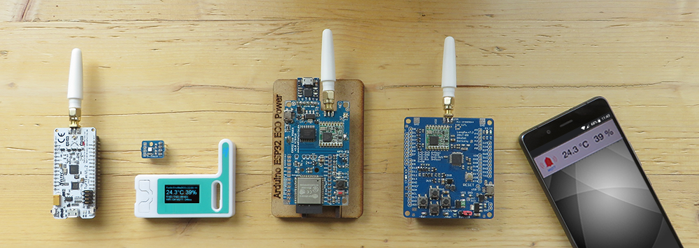
Hi, ich habe mittlerweile einige Zeit mit codieren und der Optimierung der Funkstrecke verbraucht.
Leider ist meine Anwendung bzgl. der Bebauung und Topologie kniffelig obwohl es ’nur‘ 850m sind.
Deshalb habe ich mir das Display aus dem Link besorgt.
Wenn ich mir den Code aber ansehe, finde ich nur eine Display Ausgabe falls ein Heltec ESP Board als Basis dient.
Habe ich was übersehen ? Gibt es einen Code Kniff um die Ausgabe auf dem LCD zur Streckenanalyse zu bekommen ?
Das Display hab ich jetzt zum laufen bekommen. Kann auch einen festen Text anzeigen. Über seriell zeigt das Board die Dämpfungswerte und so weiter vom letzten empfangenen Telegram an. Kann ich diese Variablen irgendwie an das Display übergeben?
scheint alles für das ARDUINO Heltec WIFI LoRa 32 Board mit dem OLED Display SSD1306 geschrieben zu sein.
ist mir dann doch etwas zu hoch.
„viele neue Beispiele sind in Arbeit für die nächste Version.“ ist damit nur die neue Board-Version gemeint oder auch die 7.2
BTW. Zweite Frage, ich muss zugeben kein C++ Spezialist zu sein; habe nach bestem Wissen eine Anpassung der PM Applikation auf I2C Bus Sensoren codiert.
Selbst der Sleep Mode funktioniert wenn ich die Boards lokal, benachbart und mehrere Tage betreibe.
Sobald ich die Boards trenne, und wie oben beschrieben unter grenzwertigen Funkbedingungen betreibe, hängt sich die Sensor Seite innerhalb der ersten 24h auf.
Meine Frage : Kann es sein, dass das Protokoll bei Empfangsproblemen dieses Problem verursacht ?
Oder anders gefragt , gibt es eine „Referenz“ Implementierung für I2C Bus Sensoren, die stabil läuft ?
Hallo, ich versuche einen Si7021 Sensor an ein Turtle 1.1 anzuschliessen (SDA->SDA, SCL->SCL, VDD->VDD und GND->GND. Im Testprogramm wird der Sensor nicht erkannt. Muss ich zusätzlich etwas in den Einstellungen vornehmen? Vielen Dank!
Christian
How can i set up multibple turtle boards with a eagle board as station?
I want to send signals from one node to the station and use the abillity of the mesh network for extending the range with multiple nodes if the node is to far away. Do i have to set up the remote id and where, on the station, on the node or both? And if on the station, do i enter all node id’s?
And enother thing, i want to make some range test, but the nodes are going into deep sleep after a couple of minutes, even if they set as online-node. Can i disable this?
Since the eagle board should stay indoors, for better range i would put one node on the rooftop and that node should relay the signals to the eagle board station. Does this work out of the box or do i have to setup anything for that?
Another question. Is the Node-checking mode useable? This sounds like a good option for battery driven range extenders. I would only need to send some signals once a day. So the rest of the day the node could deep sleep.
At present the node checking mode is not available, it is scheduled long term for the Turtle Boards (not the ESP32 Eagle/ECO boards).
Mesh or relying is not supported by the RadioShuttle protocol and goes against the idea of LoRa communication. Relaying can be done manually by writing a simple app which forwards received messages to other known node ID’s. However this is not recommended.
Your idea: Sensor-node >> relay-node >> relay-node >> server.
In your example you keep 3 radio zones busy with traffic, with a high spreading factor a messages can easily take 2-3 seconds, in your example you keep the ISM Band 868 MHz busy for about 10 seconds, which is not good.
For the ISM band it is only permitted by a single node/server to have a bandwidth utilization of 1% per hour (3600 / 100 = 36 seconds per hour). Assuming a message need needs 3 secs this would restrict you to 12 messages per hour.
For most cases it makes sense to keep the SF7 mode where messages need about 0.25 seconds which allows 144 messages per hour.
Hello, is it possible to achieve a wireless data rate of 100kbps with a wireless link of 600m (in free space without buildings) based on real-life tests? If not, what is the data rate of the turtle board at 600m? Also at what distance can we achieve 100kbps? Thank you in advance!!!
Using SF7 it is possible to send or receive 500 bytes per second. The 600m should work assuming that there are not too many walls in between.
Please note that LoRa is not designed to sent constant data streams, instead it is preferred for small messages from time to time.
Here comes my use case for a Eagele-Board with LoRa:
I want to read the energy consumption in our house. In germany (where we leave) the good old ferrari counters are replaced with new digital electricity meters. This meters have a IR interface with some specific protocol (sml).
BUT: This meters are placed somewhere in the house, where WiFi is not available (cellar, roof) or in metal cabinets where RF does not come through. Another use case: a friend is living in a neighbourhood, where the meters of all houses are located in a room 100m from its own house.
Therefore I would give LoRa a chance.
My idea:
electricity meters with IR sender -> IR diode head (up to four heads) -> one Eagle-Board for SML decoding (with RadioShuttle-SW, as sender) -> LoRa_TX ~~~ LoRa_RX (one Eagle-Board with RadioShuttle-SW as receiver) -> MQTT
AFAIK SML decoding is not available with RadioShuttle. I would appreciate any effort for supporting and decoding SML with RadioShuttle.
Hi, tolles Projekt.
Gibt es für eine Sensor (LongRange Board im LowPower Betrieb) zu RaspBerryPi & LoRa Modul als Feststation mit Internetanbindung eine Demo Installation ?
Bzw. lässt sich diese Kombi mit der RadioShuttle SW kompilieren ?
Gruss Chris
Danke für das Feedback. Aktuell gibt es kein Beispiel für eine Anbindung zum PI. Ein Bekannter hat mal eine I2C Kommunikation zum PI entwickelt, ist aber im Lieferumfang nicht dabei.
Muss also selber programmiert werden.
PS: Langfristig wollten wir MQTT per WiFi und/oder Ethernet unterstützen. Sobald es fertig ist wird es hier dokumentiert.
Hallo, habe am Wochenende endlich die Zeit gefunden und mich mit den Boards beschäftigt. Mit der Doku kommt man sehr gut zurecht. Danke an die Macher 🙂
Das Hochladen ist erfolgreich, bis zu dem Zeitpunkt, wo der Fehler erscheint, dass das Board an dem COM, der eben noch funktionierte, nicht mehr verfügbar ist.
Auszug aus Fehlerprotokoll:
Verify 70116 bytes of flash with checksum.
checksumBuffer(start_addr=0x2000, size=0x1000) = dae9
checksumBuffer(start_addr=0x3000, size=0x1000) = 1562
checksumBuffer(start_addr=0x4000, size=0x1000) = 88f3
checksumBuffer(start_addr=0x5000, size=0x1000) = e6c8
checksumBuffer(start_addr=0x6000, size=0x1000) = f13a
checksumBuffer(start_addr=0x7000, size=0x1000) = 6cc3
checksumBuffer(start_addr=0x8000, size=0x1000) = e2d8
checksumBuffer(start_addr=0x9000, size=0x1000) = 1e6e
checksumBuffer(start_addr=0xa000, size=0x1000) = c7d0
checksumBuffer(start_addr=0xb000, size=0x1000) = 6c12
checksumBuffer(start_addr=0xc000, size=0x1000) = 9f55
checksumBuffer(start_addr=0xd000, size=0x1000) = 49a5
checksumBuffer(start_addr=0xe000, size=0x1000) = fd76
checksumBuffer(start_addr=0xf000, size=0x1000) = 554a
checksumBuffer(start_addr=0x10000, size=0x1000) = fbe0
checksumBuffer(start_addr=0x11000, size=0x1000) = 104a
checksumBuffer(start_addr=0x12000, size=0x1000) = 2827
checksumBuffer(start_addr=0x13000, size=0x1e4) = b0a
Verify successful
done in 0.074 seconds
CPU reset.
readWord(addr=0)=0x20007ffc
readWord(addr=0xe000ed00)=0x410cc601
readWord(addr=0x41002018)=0x10010305
writeWord(addr=0xe000ed0c,value=0x5fa0004)
Das Board an COM28 ist nicht verfügbar
WINDOWS 7
Arduino IDE 1.8.5
Woran kann das liegen bzw. wie lässt sich das Problem lösen?
Viele Grüße und Danke
Mario
…also es ist so, dass ich nun auch die Software auf die Board geladen bekomme. Wenn ich nun den Seriellen Monitor 3 sec nach Aufspielen des Sketches öffne, kommt folgende Meldung:
processing.app.SerialException: Fehler beim Öffnen des seriellen Ports „COM28“.
at processing.app.Serial.(Serial.java:147)
at processing.app.Serial.(Serial.java:82)
at processing.app.SerialMonitor$4.(SerialMonitor.java:101)
at processing.app.SerialMonitor.open(SerialMonitor.java:101)
at processing.app.AbstractMonitor.resume(AbstractMonitor.java:104)
at processing.app.Editor.resumeOrCloseSerialMonitor(Editor.java:2218)
at processing.app.Editor.access$2200(Editor.java:79)
at processing.app.Editor$DefaultExportHandler.run(Editor.java:2196)
at java.lang.Thread.run(Thread.java:748)
Caused by: jssc.SerialPortException: Port name – COM28; Method name – openPort(); Exception type – Port not found.
at jssc.SerialPort.openPort(SerialPort.java:167)
at processing.app.Serial.(Serial.java:136)
… 8 more
Fehler beim Öffnen des seriellen Ports „COM28“.
Herzliche Grüße
Beim Arduino Zero wird der USB-Port mal für den Bootloader genutzt aber auch für die Anwendung. In der Anwendung schalten wir USB aus, wenn nicht innerhalb von 5 Sekunden der Serial Monitor gestartet wird.
Mit einen Doppelklick auf die Reset-Taste kann der Bootloader-Betrieb wieder aktiviert werden. Damit sollte es funktionieren.
Hi, ich habe mittlerweile einige Zeit mit codieren und der Optimierung der Funkstrecke verbraucht.
Leider ist meine Anwendung bzgl. der Bebauung und Topologie kniffelig obwohl es ’nur‘ 850m sind.
Deshalb habe ich mir das Display aus dem Link besorgt.
Wenn ich mir den Code aber ansehe, finde ich nur eine Display Ausgabe falls ein Heltec ESP Board als Basis dient.
Habe ich was übersehen ? Gibt es einen Code Kniff um die Ausgabe auf dem LCD zur Streckenanalyse zu bekommen ?
Gruss und vielen Dank. Christoph
Oh, genau an dem Problem bin ich auch gerade … gibt es da schon eine Lösung?
Für das Display gibt es leider keine Beispiele von uns, viele neue Beispiele sind in Arbeit für die nächste Version.
Das Display hab ich jetzt zum laufen bekommen. Kann auch einen festen Text anzeigen. Über seriell zeigt das Board die Dämpfungswerte und so weiter vom letzten empfangenen Telegram an. Kann ich diese Variablen irgendwie an das Display übergeben?
scheint alles für das ARDUINO Heltec WIFI LoRa 32 Board mit dem OLED Display SSD1306 geschrieben zu sein.
ist mir dann doch etwas zu hoch.
„viele neue Beispiele sind in Arbeit für die nächste Version.“ ist damit nur die neue Board-Version gemeint oder auch die 7.2
BTW. Zweite Frage, ich muss zugeben kein C++ Spezialist zu sein; habe nach bestem Wissen eine Anpassung der PM Applikation auf I2C Bus Sensoren codiert.
Selbst der Sleep Mode funktioniert wenn ich die Boards lokal, benachbart und mehrere Tage betreibe.
Sobald ich die Boards trenne, und wie oben beschrieben unter grenzwertigen Funkbedingungen betreibe, hängt sich die Sensor Seite innerhalb der ersten 24h auf.
Meine Frage : Kann es sein, dass das Protokoll bei Empfangsproblemen dieses Problem verursacht ?
Oder anders gefragt , gibt es eine „Referenz“ Implementierung für I2C Bus Sensoren, die stabil läuft ?
Gruss
Christoph
Gibt es eine Anleitung, welche pins zwischen Turtle (v1.1) und w5500 verbunden werden sollen, damit der w5500 genutzt werden kann?
Hallo, ich versuche einen Si7021 Sensor an ein Turtle 1.1 anzuschliessen (SDA->SDA, SCL->SCL, VDD->VDD und GND->GND. Im Testprogramm wird der Sensor nicht erkannt. Muss ich zusätzlich etwas in den Einstellungen vornehmen? Vielen Dank!
Christian
Hallo,
kennt ihr eine deutsche/europäische Bezugsquelle für das Tutle Board?
VG
Martin
Das finale Turtle Board wird Anfang Mai bei uns verfügbar sein. Details dann auf der Webseite
Gruß
How can i set up multibple turtle boards with a eagle board as station?
I want to send signals from one node to the station and use the abillity of the mesh network for extending the range with multiple nodes if the node is to far away. Do i have to set up the remote id and where, on the station, on the node or both? And if on the station, do i enter all node id’s?
And enother thing, i want to make some range test, but the nodes are going into deep sleep after a couple of minutes, even if they set as online-node. Can i disable this?
Since the eagle board should stay indoors, for better range i would put one node on the rooftop and that node should relay the signals to the eagle board station. Does this work out of the box or do i have to setup anything for that?
Grüße aus dem Landkreis Lüneburg 😉
Another question. Is the Node-checking mode useable? This sounds like a good option for battery driven range extenders. I would only need to send some signals once a day. So the rest of the day the node could deep sleep.
At present the node checking mode is not available, it is scheduled long term for the Turtle Boards (not the ESP32 Eagle/ECO boards).
Mesh or relying is not supported by the RadioShuttle protocol and goes against the idea of LoRa communication. Relaying can be done manually by writing a simple app which forwards received messages to other known node ID’s. However this is not recommended.
Your idea: Sensor-node >> relay-node >> relay-node >> server.
In your example you keep 3 radio zones busy with traffic, with a high spreading factor a messages can easily take 2-3 seconds, in your example you keep the ISM Band 868 MHz busy for about 10 seconds, which is not good.
For the ISM band it is only permitted by a single node/server to have a bandwidth utilization of 1% per hour (3600 / 100 = 36 seconds per hour). Assuming a message need needs 3 secs this would restrict you to 12 messages per hour.
For most cases it makes sense to keep the SF7 mode where messages need about 0.25 seconds which allows 144 messages per hour.
Hello, is it possible to achieve a wireless data rate of 100kbps with a wireless link of 600m (in free space without buildings) based on real-life tests? If not, what is the data rate of the turtle board at 600m? Also at what distance can we achieve 100kbps? Thank you in advance!!!
Using SF7 it is possible to send or receive 500 bytes per second. The 600m should work assuming that there are not too many walls in between.
Please note that LoRa is not designed to sent constant data streams, instead it is preferred for small messages from time to time.
Here comes my use case for a Eagele-Board with LoRa:
I want to read the energy consumption in our house. In germany (where we leave) the good old ferrari counters are replaced with new digital electricity meters. This meters have a IR interface with some specific protocol (sml).
BUT: This meters are placed somewhere in the house, where WiFi is not available (cellar, roof) or in metal cabinets where RF does not come through. Another use case: a friend is living in a neighbourhood, where the meters of all houses are located in a room 100m from its own house.
Therefore I would give LoRa a chance.
My idea:
electricity meters with IR sender -> IR diode head (up to four heads) -> one Eagle-Board for SML decoding (with RadioShuttle-SW, as sender) -> LoRa_TX ~~~ LoRa_RX (one Eagle-Board with RadioShuttle-SW as receiver) -> MQTT
AFAIK SML decoding is not available with RadioShuttle. I would appreciate any effort for supporting and decoding SML with RadioShuttle.
This is a good idea, SML decoding must be developed, maybe there is a SLM code available from somewhere in the Internet.