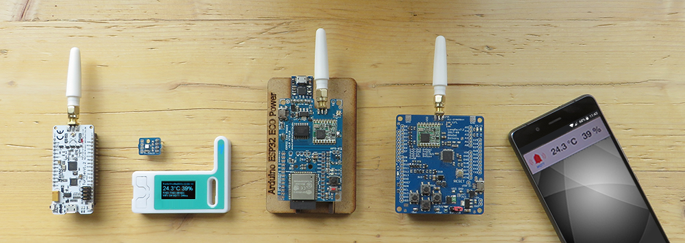
In order to make the introduction to LoRa radio technology as easy as possible, almost everything in our solution is ready to use. All boards are tested by us before delivery and loaded with a test program of the RadioShuttle software. It is only a few steps to the first own radio range tests.
We advise you to read the previous chapter The Eagle Board and its Technology. There you will find explanations of the individual components of the board, which will be discussed below.
Install Arduino IDE and ESP32 support
For proper operation, the Arduino IDE must be installed and ESP32 support must also be available:
1. Install the Arduino IDE
- Install the latest Arduino IDE which is available on the Arduino website
2. Install the “Arduino Core” extension for ESP32
Starting with version 1.6.4, Arduino allows the installation of third-party platform packages available for Windows, macOS, and Linux.
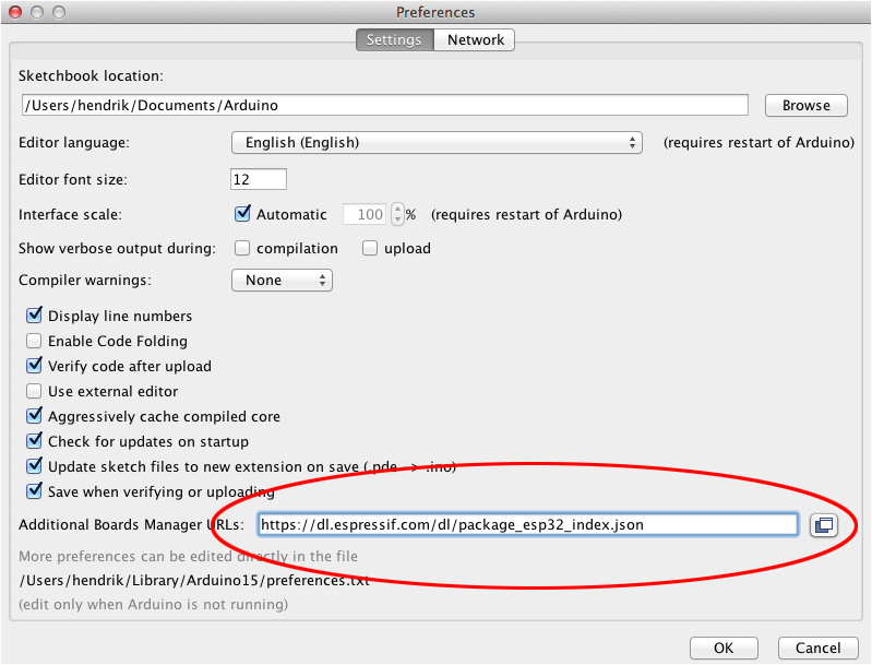
- Start Arduino and open the “Preferences” window
- Enter https://dl.espressif.com/dl/package_esp32_index.json into “Additional Boards Manager URLs” (see illustration). You can add multiple URLs, separating them with commas
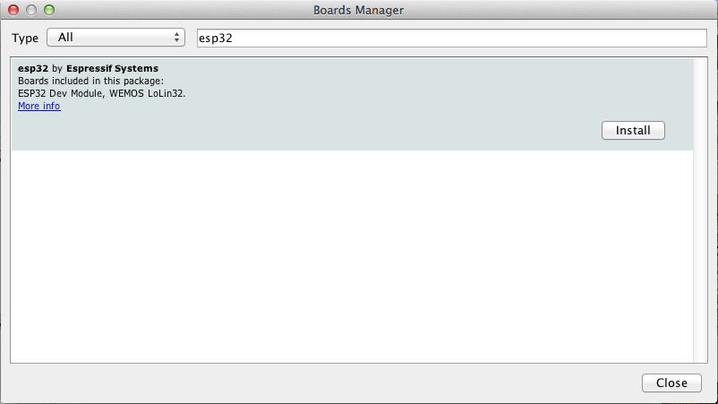
- Open “Boards Manager” from the “Tools > Board” menu and install the “esp32” platform (see illustration)
There are different board variants for the ESP32. For programming the Eagle board, the entry “Heltec WiFi LoRa 32 (V2)” must be selected from the menu “Tools > Board”:
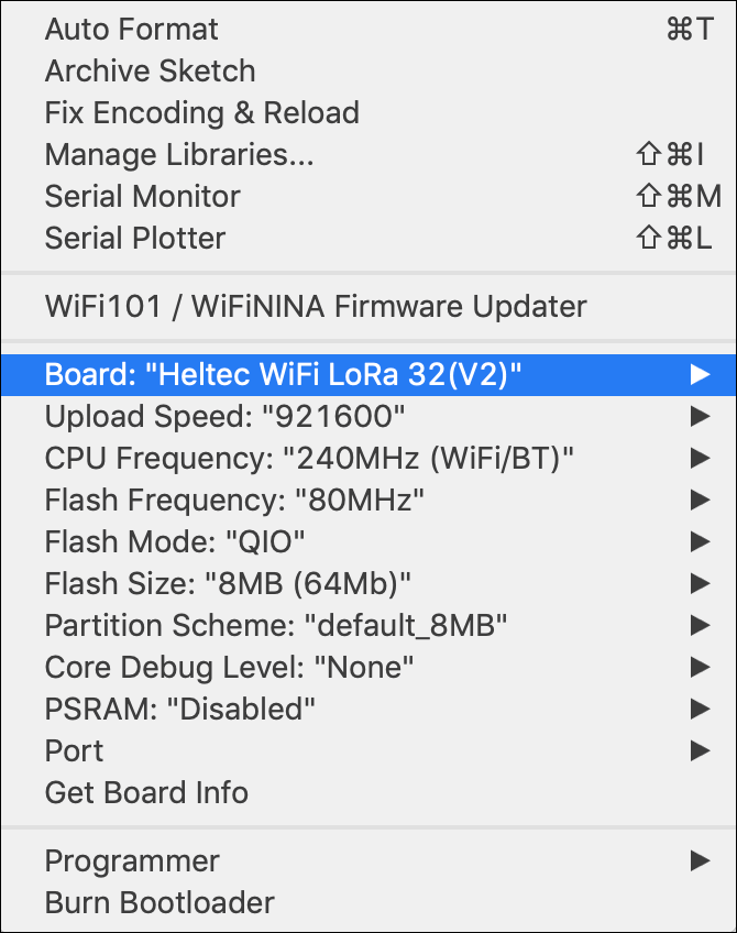
- The serial port “/dev/cu.SLAB_USBtoUART” (Mac) or “COM3” (Windows) must be selected from the menu “Tools > Port”. In the “Serial Monitor” window, select the baud rate “115200”
Note:
If the serial port is not available on your platform, you need to download the required driver first. You need the driver “CP210x” provided by Silicon Labs, Inc. It can be downloaded here.
Configure the Eagle board
The board contains an integrated USB programming adapter which will automatically turn the board into programming mode and restarts the board after a new program is uploaded. The following two steps can usually be ignored.
- Preparation for programming
The Eagle board will automatically switch into programming mode during upload. In case this does not work do the following:
Open the “Serial Monitor” window in the Arduino IDE. Afterwards, the board is switched into the programming mode by holding the “User” button while briefly pressing the “Reset” button. This is confirmed in the “Serial Monitor” window with the linewaiting for download. From now on the function “Upload” can be selected in the Arduino IDE, which loads the software into the board - Completion after programming
After the programming in the Arduino IDE has been finished, the messageLeaving… / Hard resetting via RTS pin…is displayed. Since there is no reset line on the programming adapter, the “Reset” button must be pressed briefly to make the board start with the loaded sketch
Function testing with the “Blinky” sample program
To check if the steps taken unto now were successful, the sample program “Blinky” can be used for function testing:
- In the Arduino IDE select “File > Examples > Arduino-mbed-APIs” and choose “Blinky” from the list
- Then select “Sketch > Upload” from the Arduino IDE menu
- After the program compilation process has finished
(Leaving… / Hard resetting via RTS pin…) press the “Reset” button - If everything is correct, the LED (white) should continuously flash
Solder on pin strips
The connection blocks for extensions (headers) of the Eagle boards supplied are not soldered on. If necessary, this must be done independently. The optional temperature sensor is also not soldered on in order to decide flexibly how and where the sensor is used. For the first operation it is not necessary to solder the pin strips.
Power supply
The general concept of power supply has already been explained in the technical section. In this chapter we show the selection of the different types of supply.
External power supply via USB connector
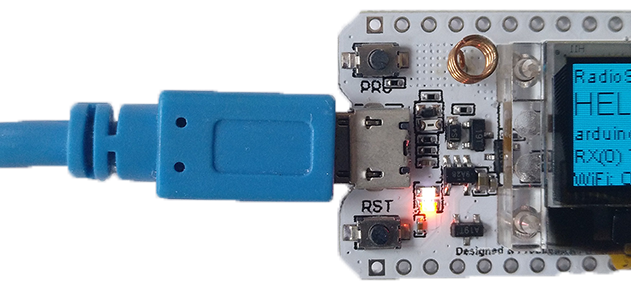
Simple operation with a USB charger, a computer or a power bank is possible via the micro-USB socket. The micro-USB input is not power-saving, as the voltage is reduced to 3.3 volts by an LDO regulator. However, this is irrelevant for a plug-in power supply unit or computer.
External power supply (5 volts)
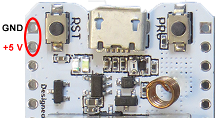
The upper pins “GND” and “5V” are located to the left of the “Reset” button. An external voltage (5 volts) can be applied here. Please note that this input is not power-saving, as the voltage is reduced to 3.3 volts by an LDO regulator.
Battery mode
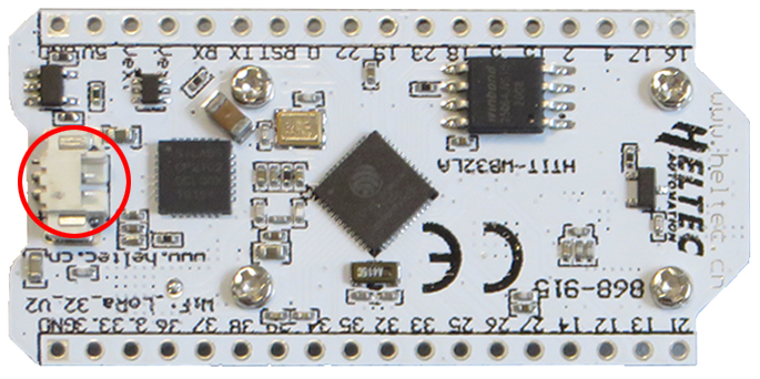
As a UPS failover support, the Eagle board can be buffered using batteries. An SH1.25 connector to connect to a battery is located on the back of the board. Rechargeable Li-ion or LiPo batteries are supported. The orange LED lights up until the connected battery is fully charged.
When the board is powered via the USB connector, or using an external power supply, the orange LED indicates the battery charging. Without a connected battery, the orange LED will continually light up. See the technical note Eagle board: disable charge LED.
Important:
Only use rechargeable LiPo or Li-ion batteries to power the Eagle board. Using a standard (i.e. non-rechargeable) battery would cause serious damage to the battery (explosion hazard) and the board if the board is powered via USB or 5 V! Never connect the USB and external 5 V supply in parallel because this will produce damages with two competing power sources.
Continue with RadioShuttle Sketch Installation for Eagle