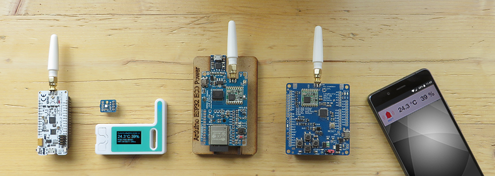
In order to make the introduction to LoRa radio technology as easy as possible, almost everything in our solution is ready to use. All boards are tested by us before delivery and loaded with a test program of the RadioShuttle software. It is only a few steps to the first own radio range tests.
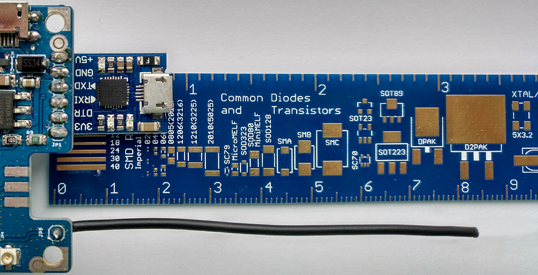
We advise you to read the previous chapter The ESP32 ECO Power Board and its Technology. There you will find explanations of the individual components of the board, which will be discussed below.
Install Arduino IDE and ESP32 support
For proper operation, the Arduino IDE must be installed and ESP32 support must also be available:
1. Install the Arduino IDE
- Install the latest Arduino IDE which is available on the Arduino website
2. Install the “Arduino Core” extension for ESP32
Starting with version 1.6.4, Arduino allows the installation of third-party platform packages available for Windows, macOS, and Linux.
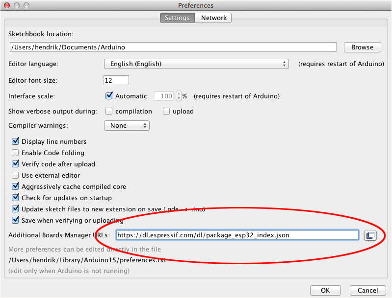
- Start Arduino and open the “Preferences” window
- Enter https://dl.espressif.com/dl/package_esp32_index.json into “Additional Boards Manager URLs” (see illustration). You can add multiple URLs, separating them with commas
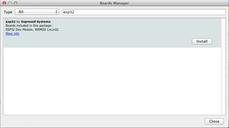
- Open “Boards Manager” from the “Tools > Board” menu and install the “esp32” platform (see illustration)
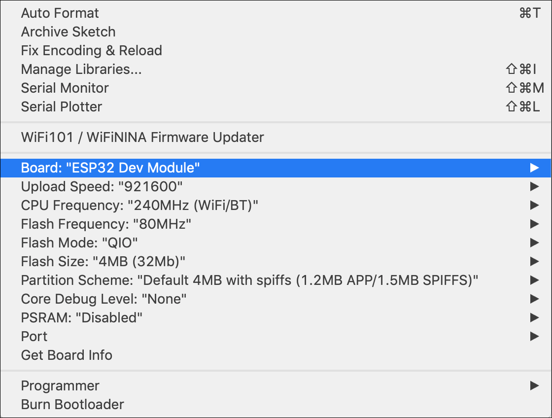
There are different board variants for the ESP32. For programming the ECO Power board, the entry “ESP32 Dev Module” must be selected from the menu “Tools > Board”:
- The serial port “/dev/cu.SLAB_USBtoUART” (Mac) or “COM3” (Windows) must be selected from the menu “Tools > Port”. In the “Serial monitor” window, select the baud rate “115200”
Note:
If the serial port is not available on your platform, you need to download the required driver first. You need the driver “CP210x” provided by Silicon Labs, Inc. It can be downloaded here.
Configure the ECO Power board
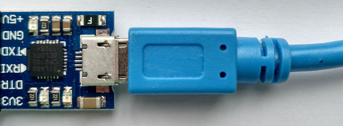
The USB programming adapter with the serial interface, which is required for the serial Arduino monitor and for programming, must be plugged in to the right of the board. Since the serial interface of this board cannot trigger either the reset or the programming mode, this must be done as follows:
- Preparation for programming
Open the “Serial Monitor” window in the Arduino IDE. Afterwards, the board is switched into the programming mode by holding the “User” button while briefly pressing the “Reset” button. This is confirmed in the “Serial Monitor” window with the linewaiting for download. From now on the function “Upload” can be selected in the Arduino IDE, which loads the software into the board - Completion after programming
After the programming in the Arduino IDE has been finished, the messageLeaving… / Hard resetting via RTS pin…is displayed. Since there is no reset line on the programming adapter, the “Reset” button must be pressed briefly to make the board start with the loaded sketch
Function testing with the “Blinky” sample program
To check if the steps taken unto now were successful, the sample program “Blinky” can be used for function testing:
- In the Arduino IDE select “File > Examples > Arduino-mbed-APIs” and choose “Blinky” from the list
- Then select “Sketch > Upload” from the Arduino IDE menu
- After the program compilation process has finished
(Leaving… / Hard resetting via RTS pin…) press the “Reset” button - If everything is correct, LED 2 (green) should continuously flash
Solder on pin strips
The connection blocks for extensions (headers) of the ECO Power boards supplied are not soldered on. If necessary, this must be done independently. The temperature sensor is also not soldered on in order to decide flexibly how and where the sensor is used. For the first operation it is not necessary to solder the pin strips.
Solder on antenna
To give you the freedom to choose the antenna technology, there is no soldered wire antenna on the board. To commission the radio module, an antenna must be connected to the ECO Power board, as radio operation without an antenna can destroy the output stage of the LoRa RFM95 module.
A simple λ/4 antenna with good performance characteristics can consist of a normal wire. With a frequency of 868.1 MHz, this results in a wavelength of 0.3453 meters for European use. Our λ/4-wire antenna must therefore be 0.086325 m = 86 mm long. After a shortening factor, the result is 82 mm. If the radio frequency of 915 MHz permitted in the USA is used, the wire must be shortened accordingly to 78 mm.
The supplied antenna wire must be soldered into the provided soldering hole (labelled “ANT”) on the bottom right of the board. From a high-frequency point of view, care must be taken to create a clean, slim solder joint. The wire must not protrude from the bottom of the soldering hole. Only after soldering is the antenna shortened for the desired frequency range. If you don’t want to set any world records in range, you don’t have to pay attention to the ½ mm …
Power supply
The general concept of power supply has already been explained in the technical section. In this chapter we show the selection of the different types of supply.
Programming adapter with USB connection
Note:
Connect an external power source either via the USB port on the programming adapter or via the USB port on the top right – never both at the same time!
After the programming adapter has been connected to the ECO Power board via a single-row strip (6x pin, PCB on the right) and connected to the computer using a micro-USB cable, the red LED marked “+5V” on the programming adapter must light up permanently. This indicates that the 5 volts USB input voltage is available via USB.
If a battery is inserted and no USB power supply is connected, the board runs on battery. As soon as the programming adapter is connected and the USB plug is connected to a computer or a power bank, the board runs automatically via USB power supply. For programming, the programming adapter must be connected; in this case, the additional upper USB power connector must not be connected, since the board is already supplied with power via the programming adapter.
External power supply “VDD” via external battery
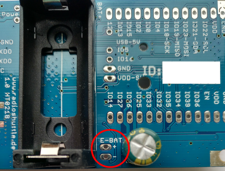
In the middle of the board, at the lower edge, there is an alternative 2-pin battery connector that must supply 2.5 to 3.6 volts, for example from a separate battery compartment. When this connector is used, no battery must be inserted in the compartment under the board. So either use the battery compartment under the board or the external battery supply.
External power supply via power adapter
Note:
Connect an external power source either via the USB port on the programming adapter or via the USB port on the top right – never both at the same time!
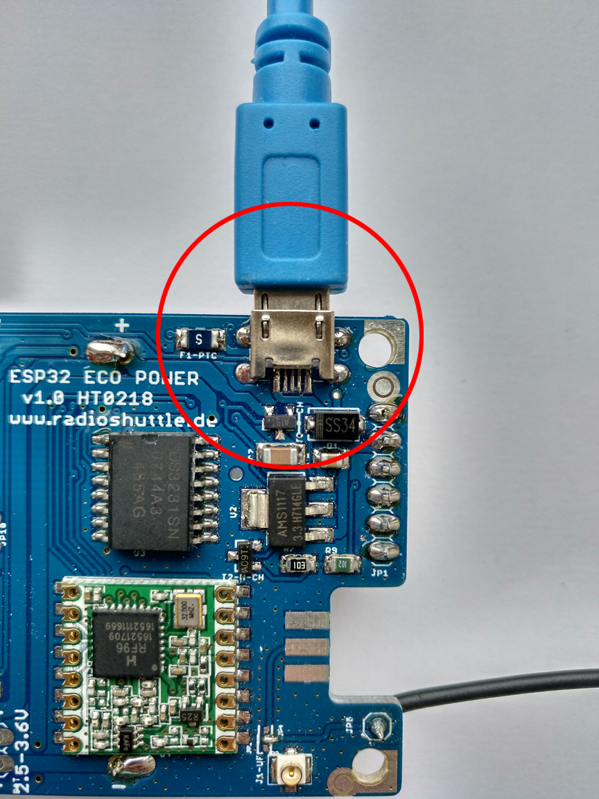
Simple operation with a USB charger, a computer or a power bank is possible via the “USB Power” micro-USB socket at the top right. Please note that in this case the programming adapter must not be plugged in. The micro-USB input is not power-saving, as the voltage is reduced to 3.3 volts by an LDO regulator. However, this is irrelevant for a plug-in power supply unit or computer.
External power supply (5 … 9 volts)
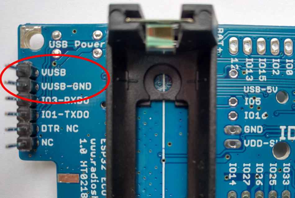
The upper pins “VUSB” and “VUSB-GND” are located on the right side of the conductor paths for the programming adapter. An external voltage (5-9 volts) can be applied here. If the power supply runs over this, the upper micro-USB socket must not be used. Please note that this input is not power-saving, as the voltage is reduced to 3.3 volts by an LDO regulator.
As a rule, the input voltage must not exceed 9 volts. Higher voltages can lead to unacceptable heating of the voltage regulator and thus to a total loss of the entire ECO Power board.
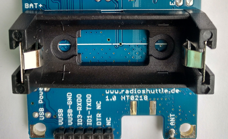
Battery mode
The battery holder on the back of the board can accommodate a CR123 battery or a LiFePo4 battery. Since the ESP32 and the RFM95 module work stably between 2.5 and 3.6 volts, only lithium batteries or LiFePo4 batteries can be used.
Operation with AA/AAA batteries
For battery operation, no alkaline batteries with 2x 1.5 volts may be used, as the minimum voltage of 2.5 volts is not reached after a short time or under load. Nickel-metal hydride batteries (NiMH) with 1.2 volts are therefore also unsuitable (2x 1.2 V = 2.4 V). In addition, it should be borne in mind that WiFi or LoRa operation requires more power than conventional batteries can supply. The use of three battery cells (AA/AAA) NiMH batteries does not work either, as the maximum voltage of 3.6 volts is exceeded.
Lithium batteries or LiFePO4 batteries should therefore be used for proper operation, as one lithium battery (3 V or 2x 1.5 V) keeps the voltage between 2.7 and 3 V. For lithium batteries, over 90% of the capacity is supplied at over 2.7 V. Operation via a LiFePO4 battery is also possible, as these keep the operating voltage at approx. 3 V and do not fall below the minimum voltage of 2.5 V.
Switching between battery operation and USB power supply is automatic. The USB power supply has priority and automatically shuts down the battery. When operating with a stationary power supply, this also has the advantage that the battery automatically takes over the power supply in the event of a power failure.
Continue with RadioShuttle Sketch Installation for ECO Power