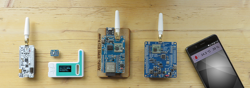
Basics
Frequencies
- Low frequencies provide better penetration at the same transmission power
- 433/868 MHz are well suited for longer ranges
- 2.4/5 GHz usually do not pass through several walls
The 868 MHz band is preferred because it is not as occupied as the 433 MHz band. On the 433 MHz frequency each radio thermometer, as well as countless other radio nodes, is unregulated. With 868 MHz, there is a set of rules that stipulates that individual nodes may not use more than 1% network load per channel. This is advantageous because there is no permanent load on the radio network. In addition, there is regulation for the 868 MHz band in Europe, 915 MHz in the USA and 920 MHz in Japan. In China, the 470-510 MHz band is used.
Antenna
- Wavelength λ (greek: lambda)
- Speed of light / frequency yields the wavelength
- At 868 MHz, an 8.5 cm wire is sufficient for a λ/4 antenna
- At 433 MHz, a 17 cm wire is suited for a λ/4 antenna
A properly adapted antenna is important because an improper antenna cannot entirely radiate the transmission power, or reflects the transmission power back into the transmission chip, which can cause damage. The antenna must also be correctly tuned to the frequency during reception. Each additional connection, each connector, and antenna cable reduces the transmission and reception power.
Positioning the antenna is also important. Ideally at a central point, so that all participants have short distances. A clear view without walls, trees or other buildings improves the range considerably.
Here is an interesting video about the function of antennas:
https://www.youtube.com/watch?v=fSoXIqBlg9M
Transmitter power output: dBm (decibel-milliwatts)
Power levels are given in logarithmic form for easy handling of both very large and very small power ratings.
Basics of dB
A basic distinction is made between power and voltage.
Power level in dBm
Lp (dB) = 10 log10(P1/P2)
P1 = Viewed size
P2 = Reference value
dBm (decibel-milliwatts)
Voltage level in dBu
Lu (dB) = 20 log10(P1/P2)
dBu (decibel-volts)
The following table impressively shows the logarithmic representation of transmission power levels, where between 0 dBm and 20 dBm a difference of 100 times the power is already visible.
| Power | dBm | Factor |
|---|---|---|
| 10 µW | -20 dBm | 0.01 |
| 100 µW | -10 dBm | 0.1 |
| 1 mW | 0 dBm | 1 |
| 10 mW | 10 dBm | 10 |
| 100 mW | 20 dBm | 100 |
| 1 kW | 60 dBm | 1 000 000 |
Note:
dB can easily be calculated:
Input 10 dB, amplifier 6 dB, cable attenuation -2 dB = 4 dB gain.
Further infos: https://en.wikipedia.org/wiki/DBm
EEVblog: https://www.youtube.com/watch?v=mLMfUi2yVu8
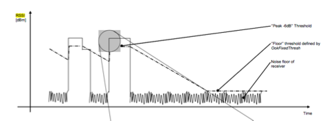
RSSI (Received Signal Strength Indication)
- Indicator for the radio reception field strength
- Example RSSI (distance from transmitter):
The examples in the table were determined experimentally with a LoRa transmitter and receiver:
| Distance | RSSI |
|---|---|
| zero | 0 |
| 1 m | -25 |
| 50 m | -70 |
| 1 000 m | -110 |
SNR
- Signal-to-noise ratio
Preamble
A preamble is a signal used in network communications to synchronize transmission timing between two or more systems. In general, preamble is a synonym for “introduction”.
- Header pattern
- Initiates the data package
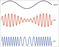
Modulation of signals
Known modulation methods
- Example: Texas Instruments radio chip: CC1101
- FSK, 2-FSK, 4-FSK, GFSK, MSK, OOK
- Many chip manufacturers
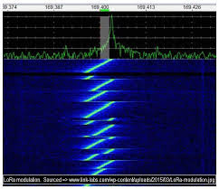
LoRa modulation
- Spread Spectrum Modulation
- Chirp Spread Spectrum (CSS)
- Known from radar technology
- Chip manufacturer (Semtech only!)
https://en.wikipedia.org/wiki/Chirp_spread_spectrum
Note:
The LoRa chip also handles the standard modulation methods.