Expansion connector set
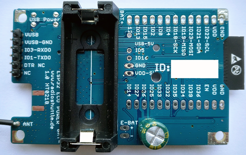
Almost all available ESP32 IO pins are located on the expansion slot. The expansion slot contains 13 pins at the top, 13 pins at the bottom, and 5 pins across between. In addition, two extension pins are provided on the programming adapter (RX/TX). All pins are labeled on the board, on the front in a small font size for space reasons, on the back in an easy-to-read font size:
We have put emphasis on making used pins that can be used in a shared way for own applications (e.g.: button, LED1, LED2, IO35 for battery voltage measurement) also available on the expansion slot. Thus, many expansion options are available.
If required, expansion boards can be plugged in on top, or alternatively they can be plugged in from below. To keep it as flexible as possible, the socket connectors (2 x 13 pins) are not soldered in, but are included in the shipping.
Standard Arduino SPI and I2C interface
The SPI and I2C interfaces are available on the expansion slot. The SPI interface is also used for LoRa, the I2C interface is already used for the clock (RTC) and for the external temperature/humidity sensor. Please note that the SPI or I2C interfaces must not be used simultaneously by the RadioShuttle software and your own applications.
I2C can be used within “loop”, as RadioShuttle does not access it at the same time.
With SPI it makes sense to use SPI only if LoRa is not active. Using the UpdateNodeStartup(RS_Node_Offline) function, LoRa can also be temporarily deactivated. Alternatively, the interrupts can be deactivated during own SPI access.
Install the wire antenna
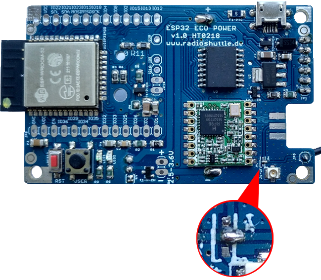
The supplied antenna wire must be soldered into the provided soldering hole (marked “ANT”) at the bottom right of the board and then shortened to 8.2 cm. Thus the antenna λ/4 is adapted for 868.1 MHz.
The exact formula for calculating the antenna length is:Wavelength = speed of light / frequency
For λ/4, this value must be divided by 4 again.
Since the soldering hole itself already acts as an antenna and a shortening factor must be taken into account, 8.2 cm is sufficient.
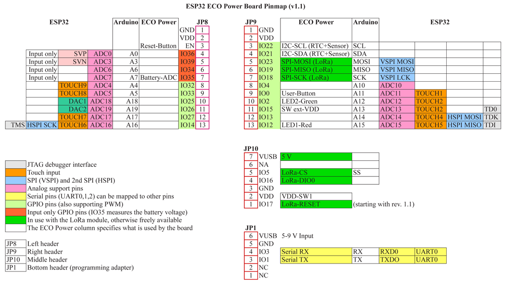
ECO Power board: pin and interrupt assignment
SMA or U.FL antenna connector
The SMA socket can easily be soldered on. Then open the antenna solder bridge to the right of the wire antenna and add a solder bridge upwards to the SMA line.
A U.FL socket is already soldered on. For this function, the antenna solder bridge to the right of the wire antenna must be opened and a solder bridge to the bottom of the SMA line must be added. Please note that the U.FL socket is only designed for a few connections, therefore we recommend using an SMA connection, which can be screwed on as often as required.
The solder bridges of the antenna must be attached in a thin and slim way in order not to influence the functionality. Only one solder bridge may be set at a time, either wire antenna, or SMA, or U.FL.
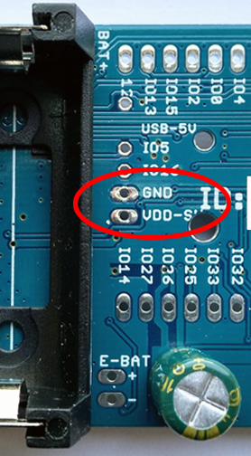
Switch on/off voltage “VDD-SW” for external loads
An internal voltage switch allows external power consumers to be switched on and off so that they do not consume power permanently. The IO pin “EXT_POWER_SW” is defined in the file “xPinMap.h” of the RadioShuttle software for switching. It can be switched to either “EXT_POWER_ON” or “EXT_POWER_OFF”. The measurement of the battery voltage, which is measured via the “BAT_POWER_ADC” ADC pins, is attached to the “VDD-SW” cable. Extended functions of the RTC clock are also already used on the “VDD-SW” line. To ensure that the board requires as little power as possible, the “VDD-SW” is usually switched off.
ECO Power board: perform a reset
The ECO Power board has no possibility to carry out a reset for programming via USB. The serial control line used with other modules is not available in the programming adapter. Therefore, a special button combination is required for programming, all details are described in the chapter Commissioning.
5 V pin on expansion slot
The USB 5 V pin on the expansion slot is directly connected to the 5 V pin of the programming adapter or to the external micro-USB power supply. A resettable fuse (500 mA) is available for external micro-USB power supply. However, there is no fuse for power supply via the USB programming adapter. In battery operation without USB power supply, no voltage is applied to the 5 V pin.
If an external power supply is connected via the programming adapter, then this can also be higher than 5 volts (max. 9 volts). Therefore, the use of the direct USB 5 V cable should be handled with care; a short circuit can sometimes destroy the computer USB port, as with other USB consumers as well.
Temperature and humidity sensor
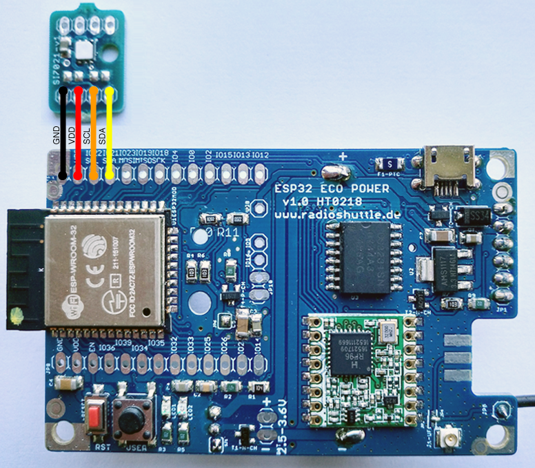
The sensor offers the possibility to measure the exact temperature and humidity in a very energy-saving way. The white felt on the sensor must not be removed, as it has a protective function so that the sensor works properly. A Silicon Labs “Si7021-A20-GM1” sensor is used, the driver is included in the RadioShuttle software.
Connect the sensor
The sensor is connected via I2C bus and requires four lines (GND, VDD, SCL, SDA). The following simple installation options are available:
- Installation onto the upper left of the board
- Installation at the top left on the back side the board
- External installation via extension cable (not included), e.g. outside the housing or directly on a heater, etc.
Please pay attention to the order of the pins (“GND” is outside); the sensor has two connection sides and can be turned so that one side fits depending on the installation (top or bottom).
Note:
Two components (optional resistors) on the sensor are intentionally not equipped, they are I2C pull-up resistors, which are already included as 10k on the main board. For an external sensor with long leads, it may be useful to solder two 1k resistors (included) to obtain stable signals. An additional option is to reduce the I2C speed. We will share our experience here later.
Software use of the sensor
If connected, the sensor is permanently active, but only requires approx. 1 μA as long as no sensor values are read. When the ECO Power board is switched on (power supply on or reset), the sensor is initialized only once and the temperature is output with the start messages. If the board is in “deepsleep” (“RadioShuttle RS_Node_Offline”), the sensor values are automatically measured and displayed again when waking up periodically (approx. every 10 seconds). The code for this can be found in the file “RTCUtil.cpp” of the “RadioTest” example.
  if (sensorSI7021->begin()) {
      hasSensor = true;
      dprintf("%s: Rev(%d)  %.2f°C  Humidity: %.2f%%", sensorSI7021->model, sensorSI7021->revision, sensorSI7021->readTemperature(), sensorSI7021->readHumidity());
  } else {
    delete sensorSI7021;
    sensorSI7021 = NULL;
  }
Note:
For this, “FEATURE_SI7021” must be defined in the “xPinMap.h” file.
It is recommended not to unnecessarily read out the sensor permanently, as each readout of the values takes time and consumes power during this time. Reading out the temperature takes approx. 13 ms, that of air humidity approx. 20 ms. During this time the ESP32 MCU is active.
Measuring the battery voltage
To measure the VDD supply voltage (approx. 3.3 volts when powered via USB, approx. 3.0 volts with battery operation) a measuring device is provided on the board. The battery voltage is displayed with an accuracy of about 100 mV. The voltage is measured and displayed when booting or resetting. The GetBatteryVoltage() function in the “RTCUtil.cpp” file measures and returns the voltage.
Accuracy of the ESP32 analog-to-digital converter (ADC)
In order to significantly increase the accuracy of the ADC measurements on the ECO Power board, the internal voltage reference of the ESP32 processor is measured during the production of the ECO Power boards and is internally stored in the eFuse memory. The function prop.GetProperty(prop.ADC_VREF, 1100); allows retrieving the value in millivolts to make an accurate calculation of the ADC measurements. Since almost every ESP32 module has a deviation in its internal reference voltage (1.100 volts), the calibration of the ECO Power boards for more accurate ADC measurements is of great advantage.
The internal ESP analog reference voltage is approx. 1.100 volts (“Attenuation ADC_0db” setting), other reference voltages (e.g. 6 dB = approx. 2.2 volts) are only derived from the internal reference 1.100 volts (0 dB). For ADC mesurements it is therefore recommended to use the 1.100 volts reference voltage (“ADC_0db”) right away because it was measured and therefore calibrated during the production of the ECO Power board.
The ADC offers an accuracy up to 12 bit (12 bit = 4,096 gradations) in a voltage range of 0-1.100 volts (reference voltage aprox. 1.100 volts). Unfortunately, these 4,096 gradations of the ESP32 internal ADC are non-linear, which impairs the accuracy of the ADC measurements. For achieving more accurate ADC measurements it is necessary that both internal converters, ADC0 and ADC1, create and use their own lookup tables for linearization.
As already mentioned before, accurate ADC measurements are only limited, or only possible with increased calibration effort. A topic on which the manufacturer, Espressif Systems, must continue to work.
ESP32 “deepsleep” and wakeup
During “deepsleep” (e.g. in the “Node Offline” mode) the MCU is shut off for energy saving reasons. The only unit running during “deepsleep” is an internal ESP32 clock (RTC, not to be confused with the external RTC!), which wakes up the MCU on external events. These external events can be GPIO pin changes or a periodic wake-up function.
The following pins support the wake-up function in the “deepsleep” mode:
IO 0
IO 2
IO 4
IO 12-15
IO 25-27
IO 32-39
In addition, the MCU becomes briefly active every 10 seconds and makes LED1 briefly flash as an activity indicator. However, this is done without starting up the MCU completely. Every minute (definable) the MCU is completely started to allow programs to periodically check if there is any task to do – this saves power. The following functions affect the sleep time and the number of passes:
| Function | Default | Min … Max |
|---|---|---|
| ESP32SetDeepSleepDuration(int ms) | 10 000 ms | 200 … 1 200 000 ms |
| ESP32SetDeepSleepBlinkDuration(int µs) | 100 µs | Recommended up to 10 000, to avoid a significant increase in energy consumption |
| ESP32SetDeepSleepWakeupInterval(int count) | 6 passes | After the passes have been completed, a wake up takes place (total time = passes x duration) |
ESP32 “sleep” and wakeup
The simple sleep() function is used when there are no tasks left to do. It lets the current CPU sleep and waits for events such as interrupts, timer, etc. The complete memory is preserved and the peripheral continues to run. Usually a system interrupt occurs 1 000 times a second, therefore LED1 (green) lightly flickers. The “sleep” function also saves energy, preventing the CPU from heating up. However, despite “sleep”, approx. 55 mA are still required, in “deepsleep” merely approx. 7 µA.
The sleep() function is executed within the loop() function as soon as no task is to do anymore. An infinite loop within the loop (polling) is not recommended and should be avoided. Clean programming should be event-driven and not use polling. This applies not only to the ESP32 but to all programs, also under Windows, Linux, Mac, and in particular in embbeded applications.