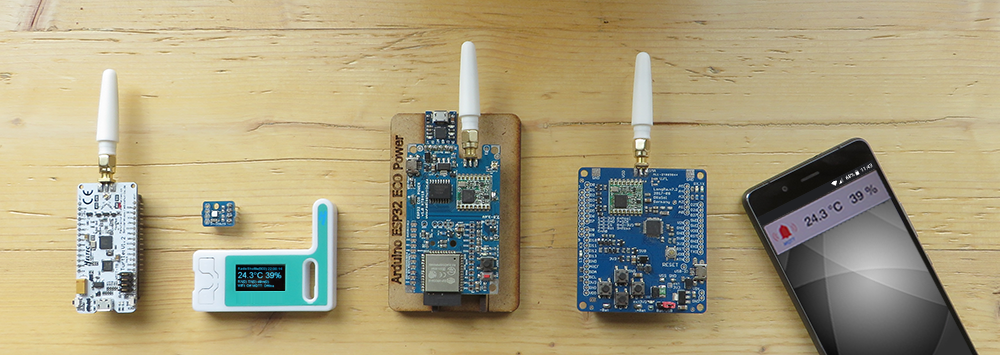
In order to make the entry into LoRa radio technology as easy as possible, almost everything is already set up in our solution. All boards are tested by us before delivery, flashed with the Arduino/Genuino Zero Bootloader and loaded with a test program of the RadioShuttle software. It’s only a few steps to your first radio transmission distance tests.
We advise you to read the previous chapter The LongRa Board and its Technology. There you will find explanations of the individual components of the board, which will be discussed below.
Arduino Zero installation
Arduino IDE installation instructions for the “Arduino/Genuino Zero” can be found here: https://www.arduino.cc/en/Guide/ArduinoZero
There are different programs for the various Arduino boards. For programming the LongRa board, select in the “Tools > Board” menu the entry “Arduino/Genuino Zero (Native USB Port)”.
Make sure that “Atmel SAMD Core” support for Arduino Zero (see link above) is installed in the “Board Manager”. Otherwise “Arduino/Genuino Zero (Native USB Port)” will not be available in the pop-up list.
Special features of the LongRa board
If “Serial Monitor” is not active, the RadioShuttle software switches off the Arduino Zero USB port for energy saving reasons. This is indicated by a short flashing LED 13 (on the left side of the board near “ID13”) after a restart.
LED 13 status modes:
- Pulse light (light/dark)
The board is ready for programming. By pressing the “Reset” button twice, you will reach this status - On
The board is running. The “Serial Monitor” USB interface is active - Flashes briefly every 5 seconds
The board is in sleep mode for power saving reasons and expects events (keystroke or similar). USB is inactive because the serial monitor has not been opened within five seconds - Permanently flashes several times per second
Button “A” was pushed during booting or during the reset, so the board waits for a serial monitor conection. Only after successfully opening the “Serial Monitor” window the software starts and the LED stops flashing
To use the USB port for programming or for the serial monitor, the “Serial Monitor” window must be opened within 5 seconds after restarting. Alternatively, the “Reset” button can be pressed twice in quick succession, enabling the bootloader to activate the USB interface for programming.
Solder pin headers
With the delivered LongRa boards v7.2, the Arduino connection headers are not soldered on. This must be done independently if necessary.
Solder antenna
To offer all the freedom when choosing the antenna technology and the sensor connection, only the voltage selection header is soldered on the board. In order to put the radio module into operation, it is essential to connect an antenna to the LongRa board, as radio operation without an antenna can destroy the output stage of the LoRa RFM95 module.
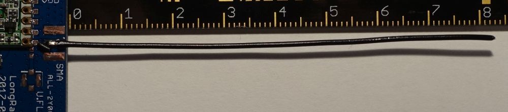
A simple λ/4 antenna with good performance characteristics can consist of a normal wire. With a frequency of 868.1 MHz, the resulting wavelength is 0.3453 meters for European use. Our λ/4-wire antenna must therefore be 0.086325 m = 86 mm long. After a shortening factor, the result is 82 mm. If the radio frequency of 915 MHz permitted in the USA is used, the wire must be shortened accordingly to 78 mm.
The supplied antenna wire must be soldered to the middle SMA-Pad on the top of the PCB. From a high-frequency point of view, it is important to ensure that a clean, slender solder joint is created. Only after soldering the antenna should it be shortened for the desired frequency range. Unless you want to set a world record, you don’t have to pay attention to the 1/2 mm …
Power supply
The general concept of the power supply was already explained in the technical section. In this chapter we will show you how to select the different types of supply.
USB connection
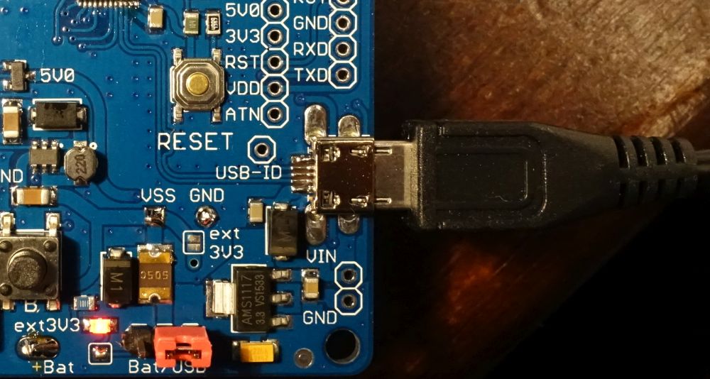
After connecting a micro-USB plug to the LongRa board, the red LED marked “ext3V3” should remain lit continuously. This indicates that the voltage converter adapts the 5 volts USB input voltage to 3.3 volts.
The “ext3V3” LED can be switched off by disconnecting the solder bridge below the LED.
If the red jumper is connected to the rightmost position (indicated by the “USB” label), the external 3.3 volts are used for the entire board as supply voltage VDD and are also available at the pins marked “VDD” for connected sensors. Instead of the jumper, the solder bridge marked “USB” can also be closed on the back of the board.
Please note that only one of the two solder bridges may be closed at a time!
External power supply via “Vin”
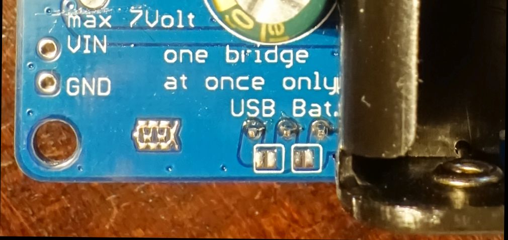
A socket for an external power supply can be soldered to the bottom right of the board (see Fig. 2: bottom right). The corresponding solder pads are marked with “VIN” and “GND”. This input uses the same voltage regulator as the USB input and therefore behaves exactly as described under USB connection.
The input voltage must normally not exceed 7 volts. Higher voltages can lead to excessive heating of the voltage regulator and to a total loss of the entire LongRa board.
Bypassing the converter for the 3V3 network
All pins marked with “3V3” (e. g. Fig. 2: top right) are supplied with power only when the 3.3 volts voltage converter is switched on by software. If the board is operated by a computer or AC adapter, the soldering bridge “ext 3V3” can be closed. This permanently connects VDD and the 3V3 network. The converter may then only be used to generate the 5 volts voltage.
Attention:
The “ext 3V3” soldering bridge must be kept open when battery operated!
Since “VDD” is located behind the jumper and behind the 500 mA fuse from the voltage input, the jumper must be connected to the “USB” position to switch on the board, despite the “ext 3V3” soldering bridge.
Battery operation
The battery holder on the back of the PCB can hold 2 AA cells. Since the Arduino Zero and the RFM95 module work stably between 2.1 and 3.6 volts, two alkaline manganese batteries with 1.5 volts, nickel-metal hydride rechargeable batteries with 1.2 volts or nickel-zinc rechargeable batteries with 1.6 volts cell voltage can be used here.
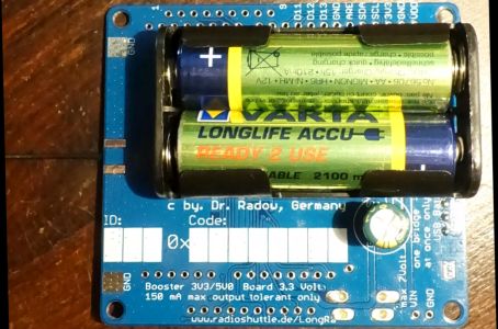
To select battery operation, either the jumper as shown in Fig. 2 must be set via the plug-in contacts marked “Bat” or the soldering bridge of the pad “Bat” on the rear side of the circuit board as shown in Fig. 3 must be closed. During battery operation, the 3.3 volts voltage regulator is completely isolated from “VDD” and therefore does not consume any valuable battery power.
The output voltages at the pin headers (“3V3” and “5V0”) are generated by the booster via software control from the available battery voltage.
Please note that only one of the two voltages can be generated at a time. Sensors with different voltages must therefore always be activated one after the other.
Continue with RadioShuttle Sketch Installation for LongRa
10 September 2017 – Rainer Radow