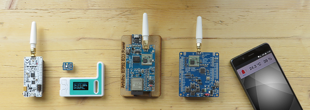
Install the wire antenna
The supplied wire antenna must be soldered to the middle SMA-Pad on top of the PCB and then shortened to 8.2 cm. The antenna is adapted to λ/4 for 868.1 MHz.
The exact formula for calculating the antenna length is:Wavelength = Speed of light / Frequency
For λ/4 this value must be divided by 4 again.
Since the SMA pad also functions as an antenna, 8.2 cm is sufficient.
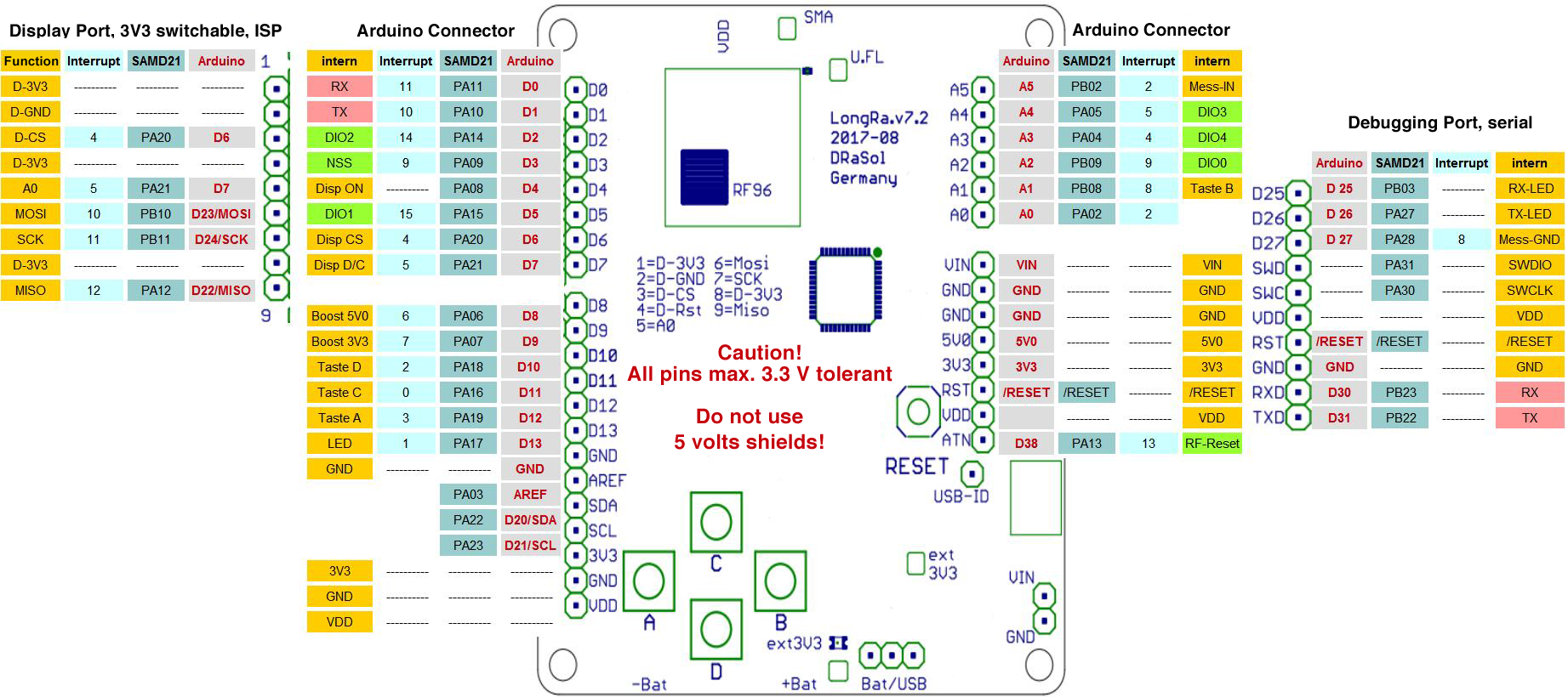
LongRa board: Pin and interrupt assignment
Pin assignment up to board revision 7.2
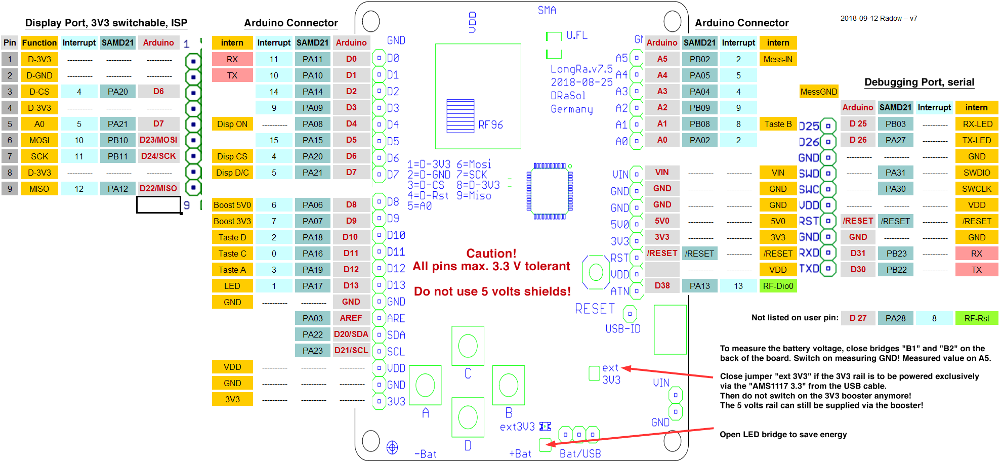
Pin assignment for board revision 7.5 and newer
SMA or U.FL antenna connector
The SMA socket can easily be soldered on.
For a U.FL socket, disconnect the antenna cable underneath the SMA connector and close the solder bridge to the left of the U.FL connector.
Switch on voltage 3.3 V or 5 V
An internal voltage transformer (booster) generates the 3.3 V or 5.0 V from the input voltage. The “PinMap. h” file of the RadioShuttle software contains the GPIO pins for switching. At present, either 3.3 V or 5 V can be switched.
Note:
The switchable booster is only available from LongRa version 6.3 or newer
Switch on voltage for monitor connector
After the booster has switched on the 3.3 V, the external monitor connection can be switched on and off. A special power cut-off ensures that the power supply of the screen is disconnected when switching off 3.3 V and also from GND. The screen can be switched on and off via pin PA08 (Arduino D4).