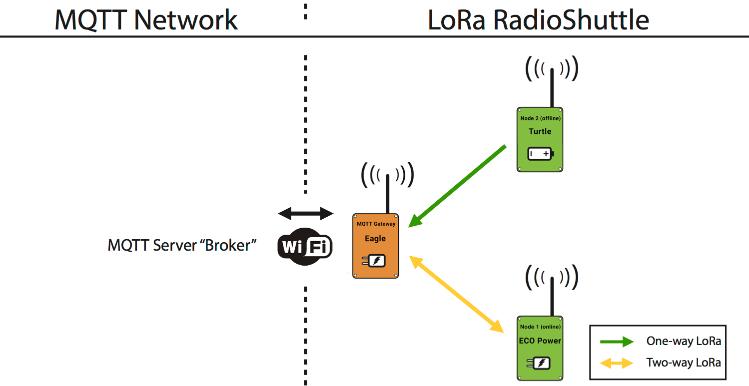
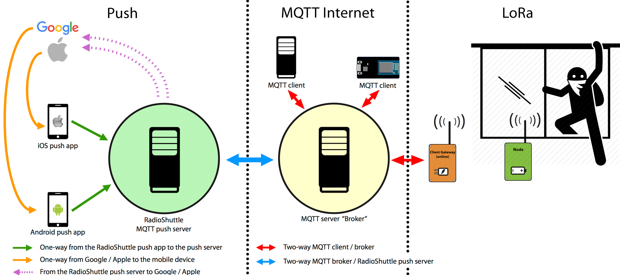
The MQTT Gateway brings peer-to-peer LoRa nodes into the Internet and vice versa. This documentation will guide you through this step by step. The gateway application is complete and does not require any programming for its operation. However, the entire LoRa gateway source code is available and can be customized when needed.
This guide will start with basic setup and will add more capabilities further down, including receiving messages from LoRa on a mobile phone.
If you follow the instructions in this guide you should be able to get everything running in about 20 minutes.
Features of the MQTT gateway
- RadioShuttle LoRa peer-to-peer protocol support
- MQTT message forwarding to specific LoRa nodes
- LoRa message forwarding to a MQTT server (also named MQTT broker)
- Extensive status reporting on OLED display (additional logging on the serial monitor)
- Automatic connect/re-connect to a WiFi network (and/or alternate WiFi network)
- Automatic connect/re-connect to a MQTT server (and/or alternate MQTT server)
- Automatic clock update via NTP (on startup and once a week)
- Operation monitoring by watchdog and reboot if it is not responsive
- SSL encryption support for MQTT communication (mqtts)
- AES encryption support for LoRa messages
- Support for 1000 LoRa nodes
Preparation
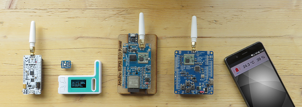
- Make sure you have a LoRa node handy, e.g. an ECO Power or Turtle Board, or a second Eagle Board.
- Make sure you have the Arduino IDE installed and running. For details see the Commissioning page.
- Make sure you have an MQTT account with username, password, hostname, port, and topic available.
- Ensure you have your WiFi SSID and password at hand.
Configure the MQTT gateway settings
- Activate the “PropertyEditor” application from the included Arduino examples by pressing the “Reset” button once and then holding the “User” button for approx. 5 seconds (until the “PropertyEditor” application starts in the “Serial Monitor” window).
- Set the following WiFi properties: WIFI_SSID, WIFI_PASSWORD (an alternate WiFi configuration is supported in case the main WiFi is not available). Optionally, set up a HOSTNAME property to give the MQTT gateway a name, e.g. “mygateway1”.
- Set the MQTT_SERVER property:
mqtt://user:password@hostname:port
or using SSL:
mqtts://user:password@hostname:port - Set the MQTT_TOPIC_GATEWAY property which is used for message exchanges with the MQTT server (the topic must also be configured/allowed on the MQTT server). An alternative MQTT server configuration (MQTT_SERVER_ALT) is supported in case the main MQTT server is not available. Optionally, set the AES password via the LORA_APP_PWD property (when using a LoRa application password, this must be set and identical on all LoRa nodes). For sending a test message to another LoRa node, you also need to specify the LORA_REMOTE_ID of the remote board.
Note:
Anonymous MQTT accounts (without username and password) are not supported because this would introduce limitations when used with the “MQTT Push Client” app which requires a username.
Install the MQTT gateway software on the Eagle board
- Load the “ESP32RadioShuttleMQTTGateway” application from the included Arduino examples. It can be found in the Arduino menu: File -> Examples -> Arduino-mbed-APIs Library.
- Select the board: “Heltec WiFi LoRa 32(V2)” from the Tools -> Board -> ESP32 Arduino menu.
When the application is started, it should connect to the WiFi network and then establish a connection to the MQTT server. The OLED display on the board will show the WiFi and MQTT status.
The display will be dimmed after a short period, shortly pressing the “User” button will turn it on again.
MQTT gateway status
An extensive status can be seen in the Arduino “Serial Monitor” log file, which logs many details including passwords of WiFi and MQTT for debugging purposes. If the passwords should not be logged, the debug option must be turned off by changing SetDebug(true) to SetDebug(false) in the gateway program (“ESP32RadioShuttleMQTT.ino”) setup() function.
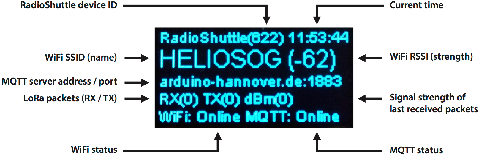
Display in “MQTT gateway” mode
Line 1
- RadioShuttle device ID of the gateway (for space reasons only the last three digits are displayed)
- The current time (in hh:mm:ss format)
Initially the program installation time is displayed, after a short period the display changes to the correct time acquired from the NTP server (assuming WiFi is available)
Line 2
- WiFi SSID (name) and WiFi RSSI (strength)
After the gateway is started, the display will show the WiFi SSID. Once the WiFi connection is established it will also show the WiFI RSSI value (e.g. “HELIOSOG (-62)”) - A WiFi RSSI of less than -85 indicates a poor WiFi signal strength
- The WiFi SSID is only displayed until the first LoRa message is received
- The last received LoRa message will be displayed (only some characters). In case the message contains binary data a hex dump of the last message is displayed
Line 3
- MQTT server address and port
Line 4
- LoRa packets received/transmitted RX(xx) TX(xx)
- Signal strength of last received packets dBm(xxx)
Sometimes the value is also called RSSI and usually ranges between -40 and -150 (with -40 dBm being nearby and -150 dBm being far away)
Line 5
- WiFi status: Offline or Online
- MQTT status: Offline or Online
To prevent the OLED display from burning in, it will automatically be dimmed after a short period. Shortly pressing the “User” button will turn it on again. The display will also be turned on when a LoRa message is received.
Setup of a LoRa node
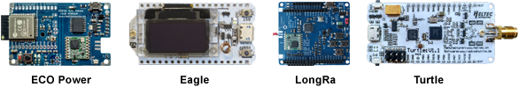
Any RadioShuttle supported board can be used, currently these are LongRa, ECO Power, Turtle and Eagle.
Arduino boards (ECO Power, Eagle, LongRa)
In this example we use one of the Arduino based boards, ECO Power.
- Install the RadioShuttle software on the ECO Power board (see Commissioning).
- Activate the “PropertyEditor” application by pressing the “Reset” button once and then holding the “User” button for approx. 5 seconds (until the “PropertyEditor” application starts in the “Serial Monitor” window).
- Set LORA_REMOTE_ID to the board ID of the MQTT gateway board (Eagle). The device ID of the Eagle board will be shown during startup in the Arduino “Serial Monitor”.
- Set LORA_RADIO_TYPE = 3 (node online) or 1 (node offline). See also the table in RadioShuttle Sketch Installation for ECO Power.
After starting the ECO Power board, pressing the “User” button will send a sample message to the MQTT gateway. This can be monitored on the gateway display. The message is also forwarded to the MQTT server.
Mbed based board (Turtle)
In this example we use our Mbed based board, Turtle.
- Install the RadioShuttle software on the Turtle board (see Commissioning).
- After the software has been successfully installed, the terminal program is started. Within 10 seconds type p and press ENTER to start the “PropertyEditor” application.
- Set LORA_REMOTE_ID to the board ID of the MQTT gateway board (Eagle):
s12=<ID of the Eagle board>
The device ID of the Eagle board will be shown during startup in the Arduino “Serial Monitor”. - Set LORA_RADIO_TYPE = 3 (node online) or 1 (node offline). See also the table in RadioShuttle Program Installation for Turtle.
By default, an empty PROG_CMDLINE property makes the software start the “RadioTestNew” program. To start another program enter the desired program code, e.g. s80=b for initially starting the “Blinky” program (see Fig. 2 in RadioShuttle Program Installation for Turtle).
After starting the Turtle board, pressing the “User” button will send a sample message to the MQTT gateway. This can be monitored on the gateway display. The message is also forwarded to the MQTT server.
MQTT messages from / to the MQTT server
Usually multiple MQTT clients are connected to the MQTT server. This can be a PC, a smartphone, or even an Arduino MQTT client. We will explain what will be sent/received between the MQTT gateway and MQTT server using the following three examples:
LoRa message received by the MQTT gateway and forwarded to the MQTT server
After the MQTT gateway has received a message from a LoRa node, it forwards it to the MQTT server. The topic looks like:loratest/HELIOS/myHost/LoRaRECV/11616/1/2
The content of the MQTT message is the LoRa message content. It is recommended to use very short messages (e.g. only a few bytes) to save energy on the LoRa node while sending, and to keep the network utilization low.
A message consist of:
- MQTT topic (
loratest/HELIOS) as specified in the gateway property MQTT_TOPIC_GATEWAY - Hostname as specified in the gateway property HOSTNAME (
myHostif empty) - The key (
LoRaRECV) indicates that the gateway forwards a received LoRa message - The number
11616indicates the LoRa node ID sending the message - The number
1is the app ID of the LoRa node sending the message (ID1is used by all example apps) - The last number indicates the reception status of the node. Valid status numbers are:
2= confirmed data has been received1= data has been received (confirmation not requested)
LoRa message from the MQTT server to the MQTT gateway
When the gateway receives a message from the MQTT server, and the configured topic matches, it will forward the message content to the remote LoRa node. The topic looks like:loratest/HELIOS/myHost/LoRaSEND/11616/1/1
- MQTT topic (
lorates/HELIOS) as specified in the gateway property MQTT_TOPIC_GATEWAY - Hostname as specified in the gateway property HOSTNAME (
myHostif empty) - The key (
LoRaSEND) indicates that the gateway should send a message to a LoRa node - The number
11616is the target LoRa node ID for this message - The number
1is the target app ID for this message - The last number indicates that a message has to be sent:
1= with confirmation0= without confirmation to the MQTT server
The second bit (2) means the message is subject to AES encryption, e.g.2AES encryption without confirmation request3AES encryption with confirmation request
confirmation message from the MQTT gateway to the MQTT server
After a message has been forwarded from the MQTT server to a LoRa node, a status message will be sent to the MQTT server to inform the it about a successful or failing messages transmission to the LoRa node. A status topic looks like:loratest/HELIOS/myHost/LoRaSTAT/11616/1/2
The message content is the status string, e.g. MS_SentCompletedConfirmed
- MQTT topic (
loratest/HELIOS) as specified in the gateway property MQTT_TOPIC_GATEWAY - A key (
LoRaSTAT) that the gateway should send a message to a LoRa node - The number
11616is the target LoRa node ID for this message - The number
1is the target app ID for this message - The last number is the completion status of the message. Valid status numbers are:
1= message transfer has been completed2= message transfer has been completed and confirmed by the receiving LoRa node3= message transfer has been aborted after a timeout occurred (3 retries issued)4= the node did not accept the message because the authorization failed
Send MQTT messages to a smartphone
After we have learned how messages are forwarded to/from the MQTT server, we go one step further and show how a message can be sent directly to a smartphone. The smartphone can even send a message to the LoRa node, via the MQTT gateway.
- Install the “MQTT Push Client” app for iOS or Android.
- Set up the MQTT account (MQTT user, password, host).
- Set up the MQTT topic in the app, e.g. “loratest/HELIOS”, as specified in the gateway settings:
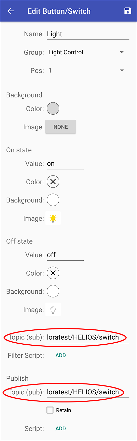
That’s it! New messages for this topic will appear on the smartphone after the LoRa node has sent a message.
Send messages from a smartphone
Add an MQTT action with the following settings:
- Name: “Hello to LoRa Node 11609”
- Topic:
loratest/HELIOS/LoRaSEND/phonename/11609/1/0 - Phonename: any name, e.g. “iPhone-Mike”
- The number
11609is the target LoRa node ID for this message - The number
1is the target app ID for this message - The last number (message send flags):
0= no confirmation1= first bit on => send a message with confirmation
The second bit (2) means the message is subject to AES encryption, e.g.2AES encryption without confirmation request3AES encryption with confirmation request
From within the “Dashboard” window in the app the action allows sending data to the LoRa node. This can be a simple control message, e.g. switching the lights on and off.
Summary
The MQTT gateway allows versatile message forwarding between the RadioShuttle LoRa peer-to-peer nodes and the IoT world via MQTT. This can be simple temperature reporting or advanced management of machines. The entire MQTT gateway does not require any programming; just enter the WiFi and MQTT parameters via the “PropertyEditor” application and it will work. The same is valid for the LoRa node. A dozen of sample applications are included, Just activate/load the proper sensor application and communication can start.
Note for advanced use
By default, all RadioShuttle sample applications use the app ID “1” within the message. A magic field in the message determines whether the message is processed or ignored. For larger projects custom app IDs can be used when registering them via the rs->RegisterApplication() function at the end of the setup() function in the example program’s “.ino” file.
When AES encrypted messages are used, the password must be set identically on all LoRa nodes and the gateway, using “PropertyEditor”. When using multiple application app IDs, the password must be specified per app ID via the rs->RegisterApplication() function.
Performance notes
MQTT messages can contain all types of data, e.g. binary data, strings, HTML, or even JSON coded messages. For WiFi networks the length of the messages is not important, whereas for LoRa networks the message length should be as short as possible. For example, the RadioShuttle temperature sensor example only uses 6 bytes or even less for transmitting humidity, temperature and battery status.
There are three main reasons to keep the message as short as possible:
- Avoids a busy LoRa radio network (allows more devices to communicate, overcomes the 1% per hour busy limit)
- Saves energy on the battery powered LoRa nodes
(For example, a 12 byte message consumes twice as much energy than a 6 byte message) - Speeds up the communication turnaround time with small messages. LoRa modulation allows large distances but has a low data rate. Small messages deliver a several times faster turnaround compared to large messages