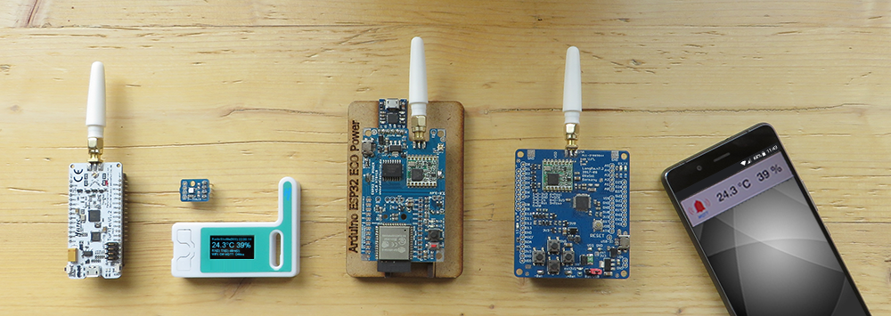
This chapter covers the installation of RadioShuttle sketches. Information about the LongRa board can be found here. For information on commissioning, please read this chapter.
Prerequisites
Activate D21 non-volatile memory for settings
“bossac” is a small utility for programming the D21 flash memory. It must be installed on the platform that you use.
Important:
“bossac” must be installed before commissioning the LongRa board for the very first time. Otherwise, all preset properties will get lost!
Download the “BOSSAC.zip” archive here. After unpacking the archive you will find the program for three different platforms:
| Name | Platform | Directory |
|---|---|---|
| bossac-linux64 | Linux | .arduino15/packages/arduino/tools/bossac/1.7.0/ |
| bossac-macos | macOS | Library/Arduino15/packages/Arduino/tools/bossac/1.7.0/ |
| bossac.exe | Windows | AppData\Local\Arduino15\packages\arduino\tools\bossac\1.7.0\ |
Copy the appropriate binary for the platform you are using into the above directory and rename it to “bossac” (“bossac.exe” for the Windows platform is not renamed). For safety reasons it is recommended to backup the existing “bossac” program beforehand, e.g. to “bossac.save”.
Install the RadioShuttle library
The complete RadioShuttle software is provided as a Zip archive and can be downloaded here, with an 8-digit code statement. The code can be found on the back of the board, e.g.: “0x67bedf1”.
Download the Zip archive containing the current software, e.g. “RadioShuttle-Arduino-2018-05-10.zip”.
Unzip the Zip archive and copy the content of the “libraries” folder into the folder “Documents/Arduino/libraries”.
Note:
In case of an already existing RadioShuttle library, the content must be completely overwritten (do not merge)!
After copying, you should see the following items in the “libraries” folder:
- “HELIOS_Si7021” (library for the temperature/humidity sensor)
- “Arduino-mbed-APIs” (additional drivers and new timer functions for the ESP32 and D21 chips)
- “Arduino-TR-064-SOAP-Library” (library for using the TR-064 protocol with the FRITZ!Box)
- “ds3231” (library for the RTC clock of the ECO Power board)
- “OLED” (library for SSD1306 displays, see Tech Info Operating the ECO Power board with an OLED display)
- “pubsubclient” (library that provides a client for simple publish/subscribe messages with an MQTT-enabled server)
- “RadioShuttle” (radio protocol software and examples)
- “RTCZero” (RTC library for the Atmel D21 chip)
- “SX1276GenericLib” (driver for the LoRa radio chip)
Customize “xPinMap.h”
“xPinMap.h” defines the pin assignment of the SAMD21 MCU with the radio chip and the other peripherals. It must must be checked for each new program that is installed and adapted if necessary. It can be found in the Arduino IDE, as an additonal tab.
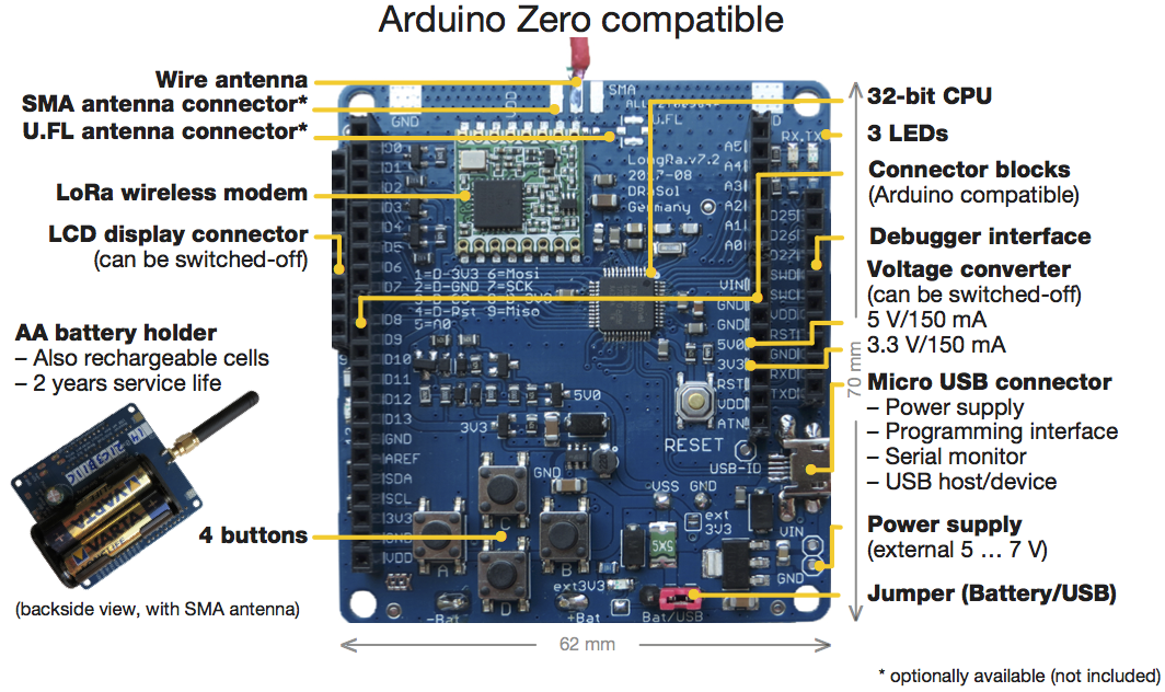
LongRa board (rev. 7.2)
In order to make the program code and the board revision match, search for the line #define D21_LONGRA_REV_720 and make sure that it is activated. If you should own a different version of the LongRa board activate the respective line and deactivate the other revisions:
// #define D21_LONGRA_REV_630  1		// board with LiPo power supply …

#define D21_LONGRA_REV_720 1 // Maker Faire Hannover revision, micro USB
LongRa board (rev. 7.5 and newer)
In order to make the program code and the board revision match, search for the line #define D21_LONGRA_REV_750 and make sure that it is activated. If you should own a different version of the LongRa board activate the respective line and deactivate the other revisions:
// #define D21_LONGRA_REV_630  1		// board with LiPo power supply …

// #define D21_LONGRA_REV_720  1		// Maker Faire Hannover revision …

#define D21_LONGRA_REV_750 1 // LongRa revision with more pins, micro USB
Sample application “PropertyEditor”
There is a memory in which settings that are to be preserved on the board after a new sketch installation can be permanently stored. It is, for example, useful to save settings such as WiFi access data or similar. The example applications “PropertyEditor” and “PropertyTest” (see in table below) can be used for this purpose. The page Non-Volatile Memory for Properties explains in detail the differences between the different memory types.
After restarting the Arduino IDE, “Arduino/Genuino Zero (Native USB-Port)” needs to be selected for the LongRa board from the “Tools > Board” menu because the Arduino IDE shows only those libraries that can run on the selected board.
Then, the “PropertyEditor” sample can be loaded from the “File > Examples > Arduino-mbed-APIs > PropertyEditor” menu item into the IDE.
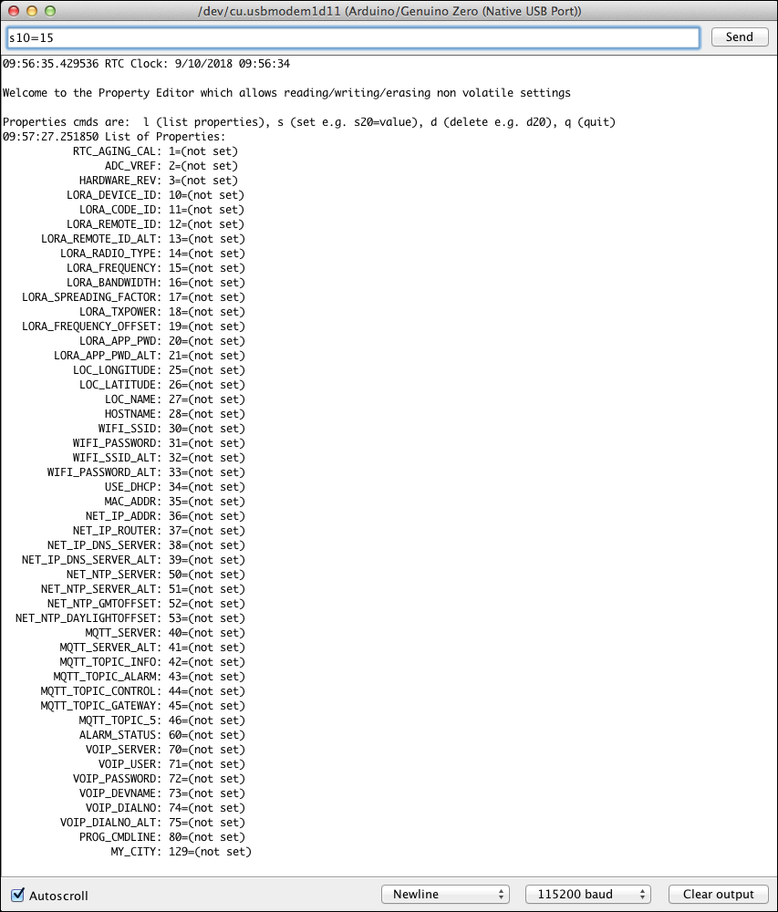
Open the “Serial Monitor” window (see Open the Arduino “Serial Monitor” window below) and load the “PropertyEditor” sketch to the LongRa board using the upload function. If this was successful the following text should appear:
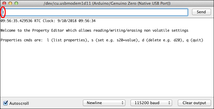
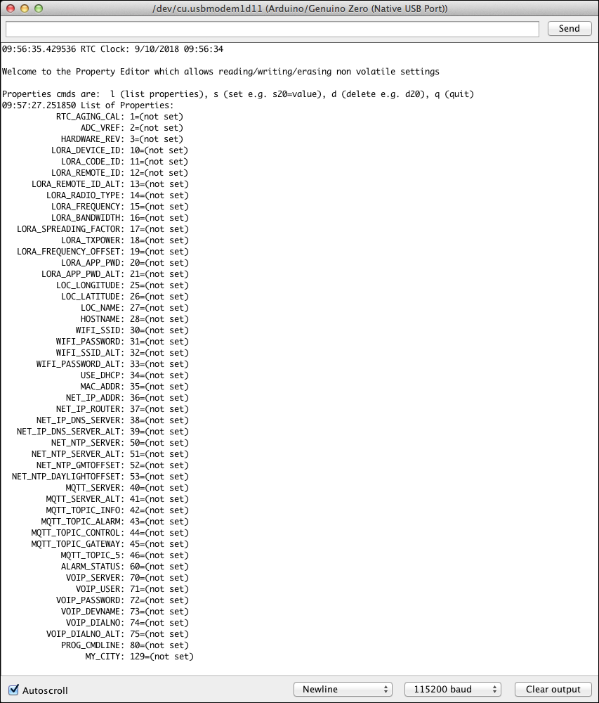
To list all available properties enter “l” (for list) in the input field, as can be seen in the figure above, and click the “Send” button:
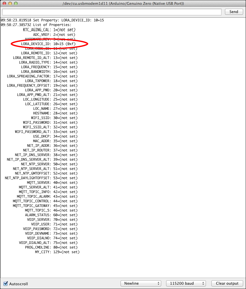
To set a property value enter “s” (for set), followed by the number of the property and the desired value. In this example the property “LORA_DEVICE_ID” (number 10) is being assigned the value “15”:
When listing the properties again, the property “LORA_DEVICE_ID” has been assigned the value “15”:
Single properties can be deleted from the memory by entering the command “d” (for delete).
Define properties for “RadioTest”
The simple RadioShuttle test application (“RadioTest”) is meant for beginners. There are two devices which communicate with each other and share a simple message. One device is called Node, the other is a so-called Station. At the touch of a button (button “A”) a message is transmitted from the node to the station. This also works the other way around, the station can also transmit a message to the node, assuming the node has been configured as Node Online (default is Node Offline).
The sample application “RadioTest” requires at least the following properties. They can be set with the PropertyEditor application:
| Property | Type | Description |
|---|---|---|
| LORA_DEVICE_ID | T_32BIT | Board device ID (preset, otherwise must be set) |
| LORA_CODE_ID | T_32BIT | Board code (preset, otherwise must be set) |
| LORA_RADIO_TYPE | T_32BIT | Type of use (not set): 1 = Node offline (Usage as a radio sensor in “deepsleep” mode) 3 = Node online (Usage as a radio sensor, always ready to receive) 4 = Station basic (Operation as server for small networks) 5 = Station Server (Operation as server for larger networks) |
| LORA_REMOTE_ID | T_32BIT | Remote station’s communications ID (not set) |
| LORA_APP_PWD (optional) | T_STR | Sets the AES-128 encryption password per app |
If not preset, enter the property value for “LORA_DEVICE_ID” in the memory. You will find it on the back side of the board (“ID:”).
Proceed in the same way with the properties “LORA_CODE_ID”, this value can also be found on the back of your board (“Code:”), “LORA_REMOTE_ID” and “LORA_RADIO_TYPE”.
If “LORA_REMOTE_ID” and “LORA_RADIO_TYPE” are not set and #define USE_DEMOBOARD_PAIR is activated in the “RadioTest.ino” file, a demo test mode between both boards is used (see Customize RadioTest.ino below).
Activate “RadioTest” sample application
After restarting the Arduino IDE, “Arduino/Genuino Zero (Native USB-Port)” needs to be selected for the LongRa board from the “Tools > Board” menu because the Arduino IDE shows only those libraries that can run on the selected board.
Then, the “RadioTest” sample can be loaded from the “File > Samples > RadioShuttle > RadioTest” menu item into the IDE. The sample allows sending messages from a node to a station, or vice-versa. It is comprised of the files “xPinMap.h”, “RTCUtil.cpp” and “RadioTest.ino”.
It is required to make the following adjustments before restarting Arduino:
Customize RadioTest.ino
The line #define USE_DEMOBOARD_PAIR can be disabled as follows:
// #define USE_DEMOBOARD_PAIR
This line has been used to automatically match the shipped board pairs.
Verify the “RadioTest” sample application
Simply push the left “A” button on the node board. This will trigger a network message from the node to the server. Then the server should receive a message. During transmission of the message, the RX and TX LED should flash for a moment. Of course this also works the other way round, pressing the “A” button on the server.
In addition, the messages are displayed in the “Serial Monitor” console.
Open the Arduino “Serial Monitor” window
Within three seconds after loading the software, or resetting the board, the “Serial Monitor” window must be opened in order to make all messages visible. The window must be opened again after loading or resetting.
If this window is not opened within five seconds, the board will switch off the USB interface (“Serial Monitor”), and LED 13 flashes shortly, confirming that the USB connector has been switched off. Switching off the USB connection is an automatic process to save energy.
Example A: Succesful start of the RadioShuttle software
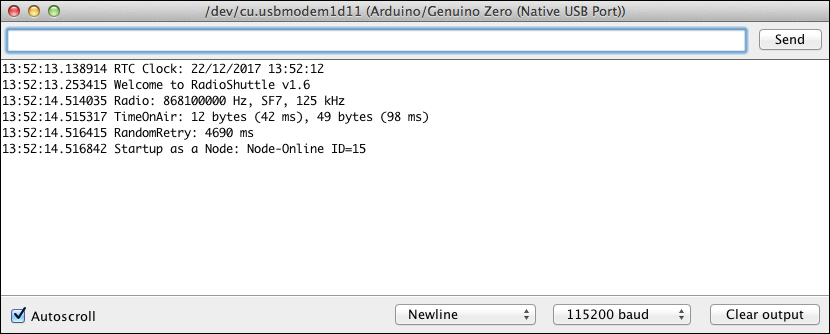
If the “Serial Monitor” is opened within five seconds of starting or resetting, you should see a message similar to the above.
Important parameters such as frequency, bandwidth and spreading factor are displayed. The “TimeOnAir” message indicates how long the data is on the move with the set parameters. If available, the time is taken from the RTC time, otherwise the compile time is used. Important is also the information of the node number (here “ID=14”) and the setting whether the system runs as a node (“Node”) or as a station.
Example B: Message successfully sent
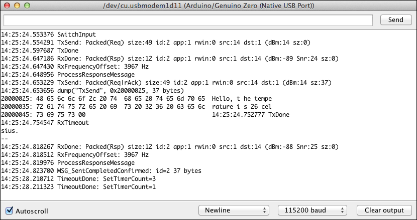
After pressing button “A”, a test message was sent to a second node. This has confirmed receipt.
Example C: Timeout on sending a message
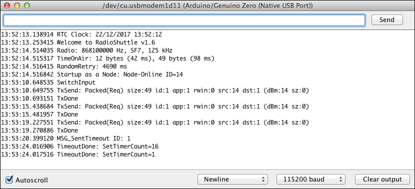
After pressing button “A”, a test message was sent. The reception was not confirmed. After three attempts, this process is aborted and a timeout error message (“MSG_SentTimeout”) appears.
Non-volatile memory for properties
There is a memory in which settings that are to be preserved on the board after a new sketch installation can be permanently stored. It is, for example, useful to save settings such as WiFi access data or similar. The example applications “PropertyEditor” and “PropertyTest” (see in table below) can be used for this purpose. The page Non-Volatile Memory for Properties explains in detail the differences between the different memory types.
Complete examples overview
| Name | Library | Description |
|---|---|---|
| Blinky | Arduino-mbed-APIs | Periodic LED flashing |
| BlinkyEnhanced | Arduino-mbed-APIs | LED flashing via timer |
| BlinkyEnhanced_C_Plus_Plus | Arduino-mbed-APIs | LED flashing via timer in C++ |
| CPUBench | Arduino-mbed-APIs | Measures the float and integer CPU performance |
| DisplayI2CSample | Arduino-mbed-APIs | Use of an OLED display (128×64 pixels, I2C). See Operating the board with an OLED display |
| HelloWorld | Arduino-mbed-APIs | Simple output printing example; explains various “printf” options |
| LongRaPowerSwitchTest | Arduino-mbed-APIs | Shows how to enable and disable 5 volts or 3.3 volts using the LongRa board |
| PMSensorRadio | Arduino-mbed-APIs | Particulate sensor; periodically measures dust in µg/m3 (PM10 and PM2.5 standards) |
| PropertyEditor | Arduino-mbed-APIs | Program for setting properties, which are stored in the board non-volatile. Remains after restarting or even after installing a new program. See also Non-Volatile Memory for Properties |
| PropertyTest | Arduino-mbed-APIs | Shows how to store properties, e.g. strings and numbers into persistent flash memory for use in sketches. See also Non-Volatile Memory for Properties |
| RadioContinuousTX | Arduino-mbed-APIs | Diagnostic program that transmits continuously, e.g. for RF antenna measurements |
| RadioShuttlePanicButton | Arduino-mbed-APIs | Very similar to “RadioShuttleSimpleNode”, but with an additional basic buzzer sound support to confirm the help searching person that the panic alarm is on its way |
| RadioShuttleRadioTest2 | Arduino-mbed-APIs | For new users and beginners, this example should be easier to use than “RadioTest” (see below); the whole LoRa specific setup code has been moved to “LoRa.cpp” |
| RadioShuttleSimpleNode | Arduino-mbed-APIs | Sends sensor data to a remote station. This includes temperature, humidity and battery status. The data is automatically sent every 30 minutes or when the user button is pressed |
| RadioTest | RadioShuttle | See detailed explanation above |
| TimerTest | Arduino-mbed-APIs | Example using multiple asynchroneous timers calling completion functions when timeout is due. Works precisely and energy-efficient |
Technical training video: Non-volatile settings (NV Property)