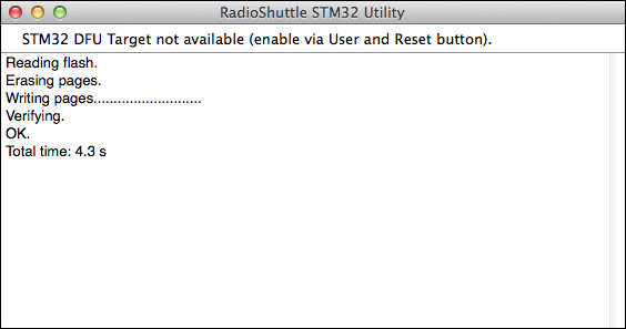
After the generated “Turtle_RadioShuttle.NUCLEO_L432KC.bin” file has been dragged & dropped into the “RadioShuttle STM32 Utility” window, the RadioShuttle software is flashed to the Turtle board.
Define properties for “RadioTest”
In order to work correctly, certain properties need to be set for the sample application “RadioTest”. These can be defined using the “PropertyEditor” application, a useful tool to write properties in the permanent (“non-volatile”) memory of the Turtle board. The next steps describe how this is done.
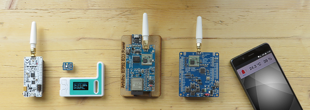
The simple RadioShuttle test application (“RadioTest”) is meant for beginners. There are two devices which communicate with each other and share a simple message. One device is called Node, the other is a so-called Station. At the touch of the “User” button a message is transmitted from the node to the station. This also works the other way around, the station can also transmit a message to the node, assuming the node has been configured as Node Online (default is Node Offline).
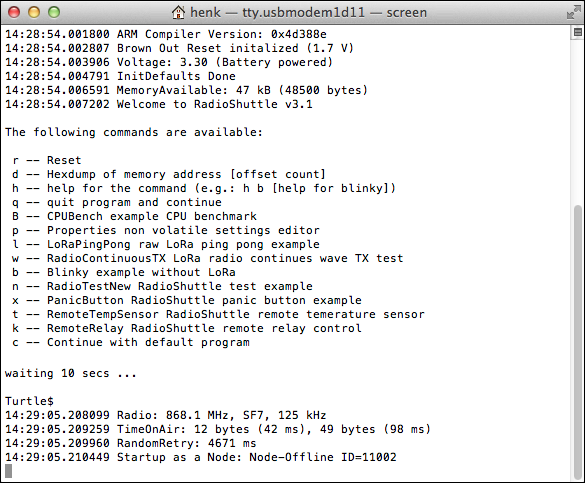
After the software has been successfully flashed under macOS, a “Terminal” program window is automatically opened (Fig. 2) showing any output of the flashed program, e.g. Arm compiler version, voltage and type of source, available memory, etc.
Note:
If “Terminal” does not start automatically (as described above), please open the menu entry “Terminal > ttyusbmodem<…>” in the “RadioShuttle STM32 Utility”.
Under Windows, the terminal emulator (e.g. “Tera Term”) must connect to the new COM port. The “Connect target serial UART to host terminal” section on the Nucleo ST-Link Interface page explains this in detail.
- After the terminal program has started, within 10 seconds type p and press ENTER (for details see 3. Flash RadioShuttle software to STM32 board).
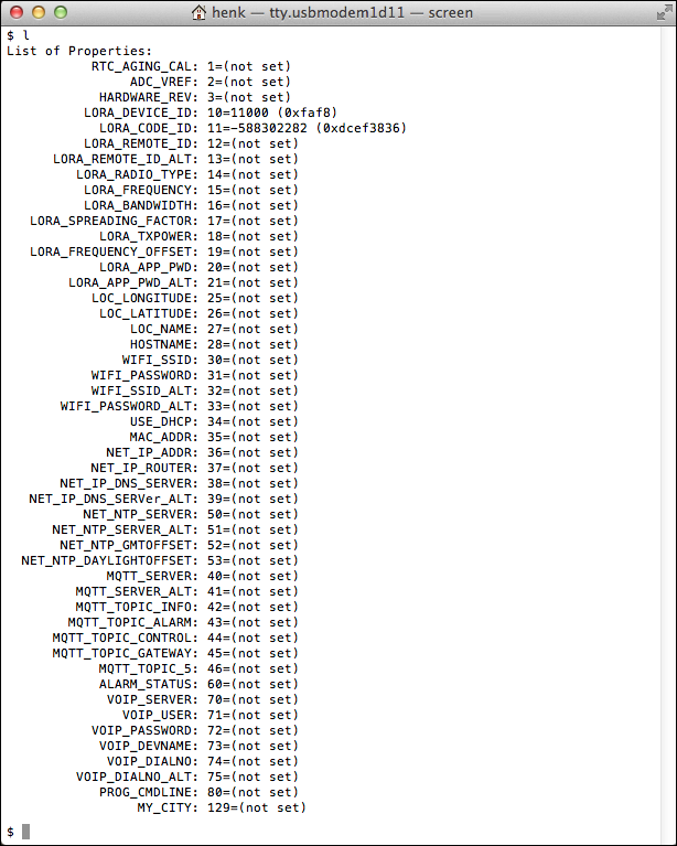
This will open the RadioShuttle PropertyEditor. This tool can be used to list all properties (l), to set a property (s<property allocation number>=<value>, and to delete a property (d) from the permanent memory.
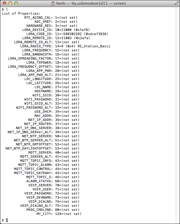
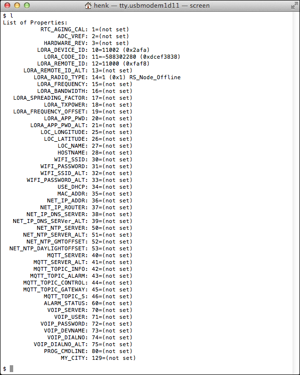
- Type l (for list) and press ENTER to see a list of all available properties (“LORA_DEVICE_ID” and “LORA_CODE_ID” are already preset, see Fig. 3).
| Property | Type | Description |
|---|---|---|
| LORA_DEVICE_ID | T_32BIT | Board device ID (preset at factory, do not touch!) |
| LORA_CODE_ID | T_32BIT | Board code (preset at factory, do not touch!) |
| LORA_RADIO_TYPE | T_32BIT | Type of use (not set): 1 = Node offline (usage as a radio sensor in “deepsleep” mode) 3 = Node online (usage as a radio sensor, always ready to receive) 4 = Station basic (operation as server for small networks) 5 = Station server (operation as server for larger networks) |
| LORA_REMOTE_ID | T_32BIT | Remote station’s communications ID (not set) |
| LORA_APP_PWD (optional) | T_STR | Sets the AES-128 encryption password per app |
As mentioned before, one device (i.e. Turtle board) functions as Node, the other as Station. The RadioShuttle “PropertyEditor” allows specifying whether the board works as a node or a station.
Station
- For the Turtle board that should be the Station, type s14=4 (for Station Basic) and press ENTER
To allow the station to send messages to a node, the “LORA_REMOTE_ID” of the node must be entered in the station board. In this case the node must be configured as Node Online to receive messages from others:
- Type s12=11002 and press ENTER
Node
- For the Turtle board that should be the Node, type s14=1 (for Node Offline) and press ENTER
To allow the node to send messages to a station, the “LORA_REMOTE_ID” of the station must be entered in the node board:
- Type s12=11000 and press ENTER
Technical training video: Non-volatile settings (NV Property)
Run the “RadioTest” sample program
After the required properties are set in both Turtle boards, the “RadioTest” example program, which is included in the RadioShuttle software, can be executed to test the configuration of the boards:
- Windows: Open “Tera Term” and set the port number and baud rate via “Setup” > “Serial port…” (see the Connect target serial UART to host terminal section for detailed information)
- macOS: Open “Terminal”
- Press the “User” button on any of the Turtle boards, Node or Station
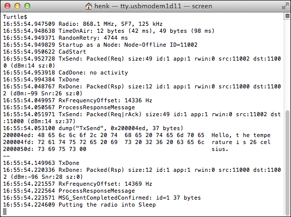
The “RadioTest” program sends a message (“TxSend”) which is received by the addressed device (“RxDone”).
In the following example (Fig. 6) the node (ID “11002”) successfully transmitted a message to the station (ID “11000”). The transmission protocol also informs about the used radio frequency, spreading factor and bandwith, the air time of the message, the Rx frequency offset, etc. Using a node in offline mode, the transmission protocol ends with the line Putting the radio into Sleep.
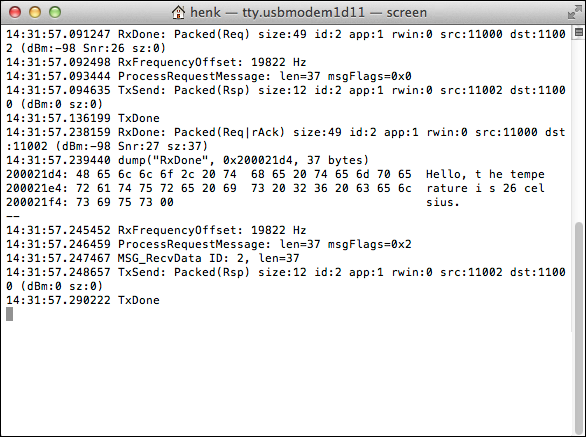
This example (Fig. 7) shows the other way round; the station (ID “11000”) successfully transmitted a message to a node in offline mode (ID “11002”).
Reset the board
If the “Reset” button is pressed, the green LED on the Turtle board quickly flashes, indicating that it waits for a terminal connection via the USB virtual COM port. If no connection has been established after 30 seconds the board continues without USB serial console.
Statuses of the LEDs in the “RadioTest” example
LED (green):
- Quickly flashing
The board waits 30 seconds to connect a terminal program (via USB virtual COM port)
- Off
The board is idle in deepsleep and has no CPU activity
- Partly flashing
The board is processing tasks, while it is busy the green LED is on
- Permanently glowing
The board is connected to a USB virtual COM port, the CPU becomes active every milliisecond to service the USB channel
- Permanently on
A polling or hanging program that runs forever without going into sleep mode

- Briefly on
After a LoRa message has been transmitted (TX)
LED (red):

- Pulse
After the RadioShuttle software has started the LED shortly flashes every 2 seconds indicating that the board is active. This can be shut off by disablingtimerUpdate()in the “main.cpp” file
- Briefly on
After a LoRa message has been received (RX)
Of course, the LEDs can also be assigned individually by the user.
The whole idea of the LEDs is to detect CPU and/or radio activity. This is very helpful to figure out whether the board is busy. For example, if the green LED is permanently lit, the board will not rest to save energy (sleep), but it is busy with USB protocols or other activity instead. The two-second impulse of the red LED mainly indicates that the board is “alive”. For final deployments with best energy savings, this behavior can be turned off.
Complete examples overview
| Name | Example | Description |
|---|---|---|
| CPUBench | CPUBench.cpp | Measures the float and integer CPU performance |
| PropertyEditor | NVPEditor.cpp | Program for setting properties, which are stored in the board non-volatile. Remains after restarting or even after installing a new program. See also Non-Volatile Memory for Properties |
| LoRaPingPong | LoRaPingPong.cpp | Raw LoRa ping pong example |
| RadioContinuousTX | RadioContinuousTX.cpp | Diagnostic program that transmits continuously, e.g. for RF antenna measurements |
| Blinky | Blinky.cpp | Periodic LED flashing using low-power timers |
| RadioTestNew | RadioTestNew.cpp | See detailed explanation above |
| PanicButton | PanicButton.cpp | Sends sensor data to a remote station. This includes temperature, humidity and battery status. It supports an additional basic buzzer sound to confirm the help searching person that the panic alarm is on its way |
| RemoteTempSensor | RemoteTempSensor.cpp | RadioShuttle remote temperature sensor, client and server implementation |
| RemoteRelay | RemoteRelay.cpp | RadioShuttle remote relay control, client and server implementation |
- Press “h” followed by the program shortcut to see the corresponding command help, e.g.
h b(“Blinky” help lines)
Technical training video: Non-volatile settings (NV Property)