This chapter covers the installation of RadioShuttle sketches. Information about the Eagle board can be found here. For information on commissioning, please read this chapter.
Install the RadioShuttle library
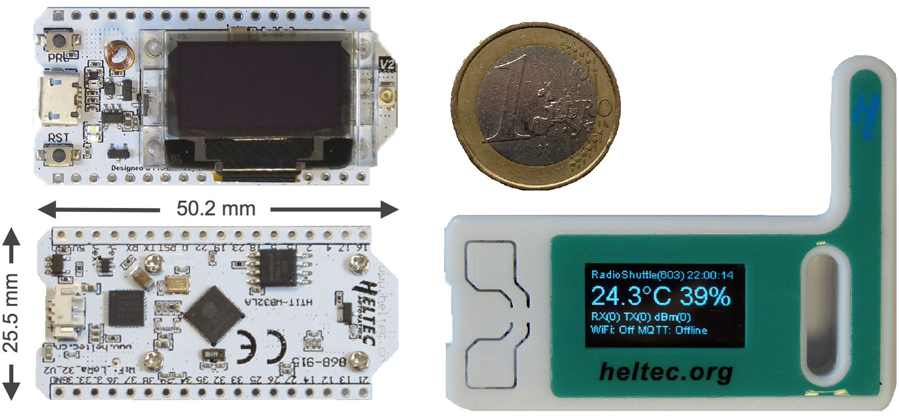
The complete RadioShuttle software is delivered in a Zip archive and can be loaded here by entering an board ID code. The ID of your board can be found on the labelled inside of the plastic box, e.g. 10998. Another option is to connect the board to the Arduino “Serial Monitor” and press the “Reset” button on the board. The default program will display the startup output including the board ID, e.g. 15:52:46.843491.
A Zip archive is loaded with the current software, e. g. “RadioShuttle-Arduino-2019-05-10.zip”.
Unzip the Zip archive and copy the content of the “libraries” folder into the folder “Documents/Arduino/libraries”.
Note:
In case of an already existing RadioShuttle library, the content must be completely overwritten (do not merge)!
After copying, you should see the following items in the “libraries” folder:
- “HELIOS_Si7021” (library for the temperature/humidity sensor)
- “Arduino-mbed-APIs” (additional drivers and new timer functions for the ESP32 and D21 chips)
- “Arduino-TR-064-SOAP-Library” (library for using the TR-064 protocol with the FRITZ!Box)
- “ds3231” (library for the RTC clock of the ECO Power board)
- “OLED” (library for the SSD1306 displays, see Tech Info Operating the ECO Power board with an OLED display)
- “pubsubclient” (library providing a client for doing simple publish/subscribe messaging with a server that supports MQTT)
- “RadioShuttle” (radio protocol software and examples)
- “RTCZero” (RTC library for the Atmel D21 chip)
- “SX1276GenericLib” (driver for the LoRa radio chip)
Customize xPinMap.h
“xPinMap.h” defines the pin assignment of the ESP32 MCU with the radio chip and the other peripherals. It must be checked for each new program that is installed and adapted if necessary. It can be found in the Arduino IDE, as an additonal tab.
At present there is no need to customize the “xPinMap.h” file because there is only the initial version of the Eagle board. If a board revision is available, we will update this section.
Sample application “PropertyEditor”
There is a memory in which settings that are to be preserved on the board after a new sketch installation can be permanently stored. It is, for example, useful to save settings such as WiFi access data or similar. The example applications “PropertyEditor” and “PropertyTest” (see in table below) can be used for this purpose. The page Non-Volatile Memory for Properties explains in detail the differences between the different memory types.
After restarting the Arduino IDE, “Heltec WiFi LoRa 32 (V2)” needs to be selected for the Eagle board from the “Tools > Board” menu because the Arduino IDE shows only those libraries that can run on the selected board.
Then, the “PropertyEditor” sample can be loaded from the “File > Examples > Arduino-mbed-APIs > PropertyEditor” menu item into the IDE.
Open the “Serial Monitor” window (see Open the Arduino “Serial Monitor” window below) and load the “PropertyEditor” sketch to the Eagle board using the upload function. If this was successful the following text should appear:
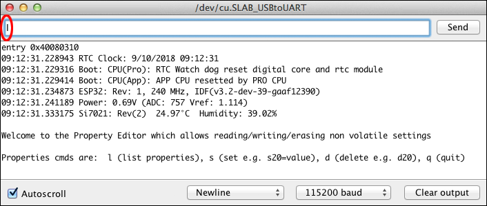
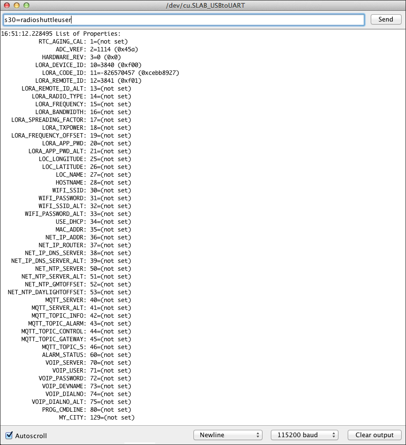
To list all available properties enter “l” (for list) in the input field, as can be seen in the figure above, and click the “Send” button:
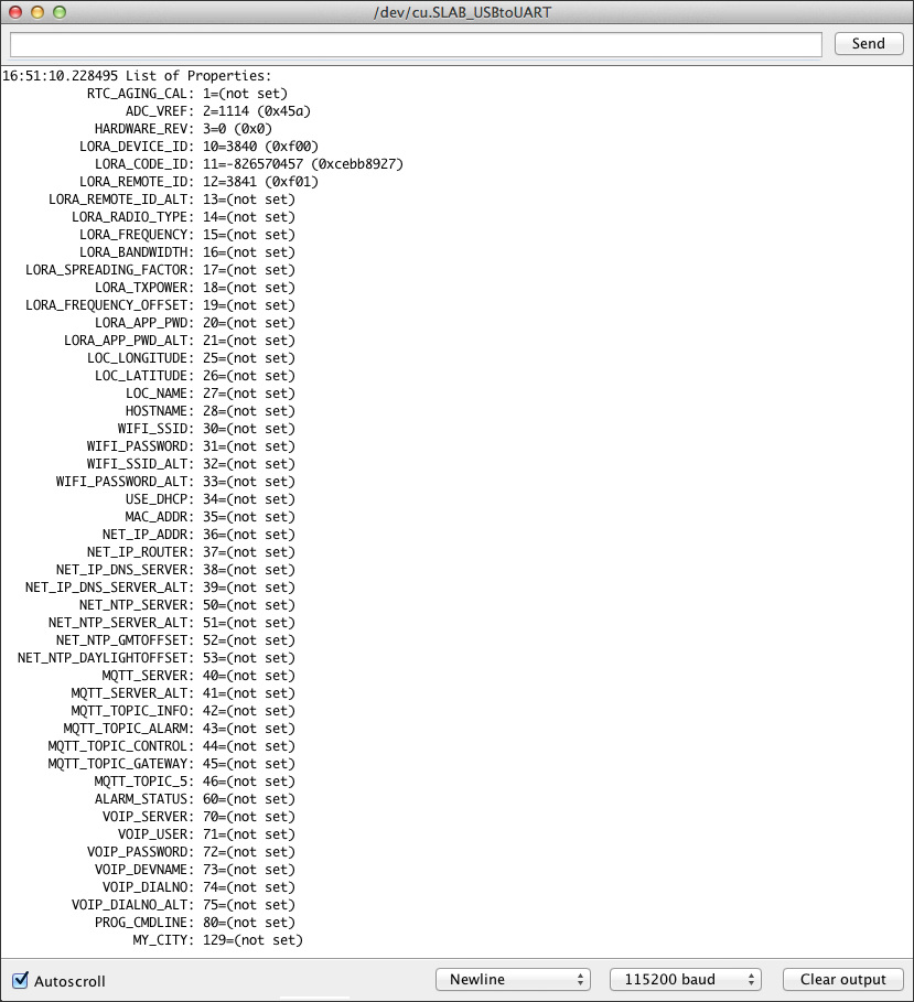
To set a property value enter “s” (for set), followed by the number of the property and the desired value. Then click the “Send” button. In this example the value “radioshuttleuser” is to be assigned to the property “WIFI_SSID” (number 30):
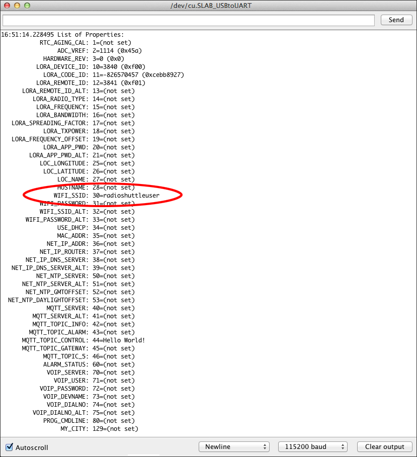
When listing the properties again, the property “WIFI_SSID” has been assigned the value “radioshuttleuser”:
Single properties can be deleted from the memory by entering the command “d” (for delete).
Define properties for “RadioTest”
The simple RadioShuttle test application (“RadioTest”) is meant for beginners. There are two devices which communicate with each other and share a simple message. One device is called Node, the other is a so-called Station. At the touch of a button (“User” button) a message is transmitted from the node to the station. This also works the other way around, the station can also transmit a message to the node, assuming the node has been configured as Node Online (default is Node Offline).
The sample application “RadioTest” requires at least the following properties. They can be set with the PropertyEditor application:
| Property | Type | Description |
|---|---|---|
| LORA_DEVICE_ID | T_32BIT | Board device ID (preset) |
| LORA_CODE_ID | T_32BIT | Board code (preset) |
| LORA_RADIO_TYPE | T_32BIT | Type of use (not set): 1 = Node offline (Usage as a radio sensor in “deepsleep” mode) 3 = Node online (Usage as a radio sensor, always ready to receive) 4 = Station basic (Operation as server for small networks) 5 = Station Server (Operation as server for larger networks) |
| LORA_REMOTE_ID | T_32BIT | Remote station’s communications ID (not set) |
| LORA_APP_PWD (optional) | T_STR | Sets the AES-128 encryption password per app |
If “LORA_REMOTE_ID” and “LORA_RADIO_TYPE” are not set and #define USE_DEMOBOARD_PAIR is activated in the “RadioTest.ino” file, a demo test mode between both boards is used (see Customize RadioTest.ino below).
Activate the “RadioTest” sample application
After restarting the Arduino IDE, “Heltec WiFi LoRa 32 (V2)” needs to be selected for the Eagle board from the “Tools > Board” menu because the Arduino IDE shows only those libraries that can run on the selected board.
Load the “RadioTest” example via “File > Examples > RadioShuttle > RadioTest” into the IDE. With this example program you can send messages from a node to a station or vice versa. It consists of the files “xPinMap.h”, “RTCUtil.cpp” and “RadioTest.ino”.
The following adjustments must be checked or made before use:
Customize RadioTest.ino
The line #define USE_DEMOBOARD_PAIR can be disabled as follows:
// #define USE_DEMOBOARD_PAIR
This line has been used to automatically match the shipped board pairs.
Verify the “RadioTest” sample application
Simply press the “User” button at the node. A network message is then sent from the node to the server. During message transmission, the transmit and receive LEDs should flash briefly. This can also be done the other way round by pressing the “User” button at the server and the node should receive a message.
In addition, the messages are displayed in the “Serial Monitor” console window.
Open the Arduino “Serial Monitor” window
It is recommended to always have the Arduino console window “Serial Monitor” open, as important messages are displayed here. Of course, a programming adapter must be connected. Reset messages such as watchdog reset, power failure reset (brownout) and boot messages are also displayed there.
Received RadioShuttle messages and sent messages are also displayed here. The function EnablePacketTrace() can be used to disable or adjust the logging of messages.
If the “Serial Monitor” window is opened later, previous messages are of course not visible.
Example A: Successful launch of the RadioShuttle software
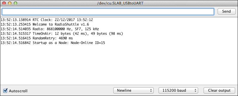
Immediately after starting or resetting the board, a message similar to the above should appear in the “Serial Monitor” window. Important parameters such as frequency, bandwidth and the spreading factor can be seen. The “TimeOnAir” message indicates how long the data is on the way with the set parameters. If available, the time is taken from the RTC time, otherwise the compile time is used. Also important is the information about the node number (here “ID=201”) and the setting whether the system runs as a node or station.
Example B: Message successfully sent
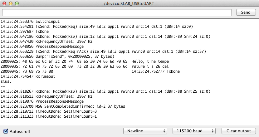
After pressing the “User” button, a test message was sent to a second node. The latter has confirmed receipt.
Example C: Timeout when sending a message
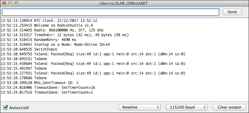
After pressing the “User” button, a test message was sent. However, reception has not been confirmed. After three attempts, this process is aborted and a timeout error message (“MSG_SentTimeout”) appears.
Statuses of the LEDs in the “RadioTest” example
White LED:
- Off
The board has no power or is in “deepsleep” mode - Shortly flashes every 10 seconds
The board runs and is in ESP32 “deepsleep” mode to consume as little power as possible, the processor is largely switched off. The short flashing indicates that it is regularly active to check if there is any task to do - Lights up permanently weak
The board is active and processes events in the Arduino “loop”. Afterwards it simply falls in a “sleep” and is woken up about 1000 times per second by the operating system - Flickering
This signals the reception of LoRa radio data - Permanently on
The board is active and works in the Arduino “loop”. While it is running, the LED is on, so if the “loop” is permanently active (continuous operation), the LED lights up continuously. For energy-optimized use, the “loop” should of course run as little as possible or only if there is something to process. The keyword is: no polling
Orange LED:
- Lights up when a connected LiPo or Li-ion battery is charged via external or USB power supply (can be disabled, see technical info Eagle board: disable charge LED)
Non-volatile memory for properties
There is a memory in which settings that are to be preserved on the board after a new sketch installation can be permanently stored. It is, for example, useful to save settings such as WiFi access data or similar. The example applications “PropertyEditor” and “PropertyTest” (see in table below) can be used for this purpose. The page Non-Volatile Memory for Properties explains in detail the differences between the different memory types.
Complete examples overview
| Name | Library | Description |
|---|---|---|
| Blinky | Arduino-mbed-APIs | Periodic LED flashing |
| BlinkyEnhanced | Arduino-mbed-APIs | LED flashing via timer |
| BlinkyEnhanced_C_Plus_Plus | Arduino-mbed-APIs | LED flashing via timer in C++ |
| CPUBench | Arduino-mbed-APIs | Measures the float and integer CPU performance |
| DisplayI2CSample | Arduino-mbed-APIs | Use of an OLED display (128×64 pixels, I2C). See Operating the ECO Power Board with an OLED Display |
| ESP32AsyncHTTPClient | Arduino-mbed-APIs | A simple HTTP client program that executes an HTTP GET oder POST request. The whole thing happens asynchronously without blocking the Arduino main loop |
| ESP32BlinkyDeepSleep | Arduino-mbed-APIs | Deepsleep example (little energy consumption); flashing every 10 sec. during “deepsleep”, LED2 flashing on wakeup every minute |
| ESP32DoorBell | Arduino-mbed-APIs | Supports a doorbell key and door opener relay. Pressing a doorbell key places phone calls via the connected FRITZ!Box. In addition, it sends an MQTT message to the “MQTT Push” app |
| ESP32FrequencyThrottle | Arduino-mbed-APIs | Changing the MCU clock to 2 MHz to save energy |
| ESP32MQTTAlarmSystem | Arduino-mbed-APIs | Small alarm system that triggers an alarm via MQTT via motion detector, including status and temperature data via display |
| ESP32MQTTClient | Arduino-mbed-APIs | Establishes a WiFi connection to an MQTT broker to send messages to it and receive registered topics from the broker |
| ESP32RadioShuttleMQTTGateway | Arduino-mbed-APIs | Receives data from nodes and forwards it to an MQTT broker. Received MQTT messages can be forwarded to LoRa nodes |
| HelloWorld | Arduino-mbed-APIs | Simple output printing example; explains various “printf” options |
| PMSensorRadio | Arduino-mbed-APIs | Particulate sensor; periodically measures dust in µg/m3 (PM10 and PM2.5 standards) |
| PropertyEditor | Arduino-mbed-APIs | Program for setting properties, which are stored in the board non-volatile. Remains after restarting or even after installing a new program. See also Non-Volatile Memory for Properties |
| PropertyTest | Arduino-mbed-APIs | Shows how to store properties, e.g. strings and numbers into persistent flash memory for use in sketches. See also Non-Volatile Memory for Properties |
| RadioContinuousTX | Arduino-mbed-APIs | Diagnostic program that transmits continuously, e.g. for RF antenna measurements |
| RadioShuttlePanicButton | Arduino-mbed-APIs | Very similar to “RadioShuttleSimpleNode”, but with an additional basic buzzer sound support to confirm the help searching person that the panic alarm is on its way |
| RadioShuttleRadioTest2 | Arduino-mbed-APIs | For new users and beginners, this example should be easier to use than “RadioTest” (see below); the whole LoRa specific setup code has been moved to “LoRa.cpp” |
| RadioShuttleSimpleNode | Arduino-mbed-APIs | Sends sensor data to a remote station. This includes temperature, humidity and battery status. The data is automatically sent every 30 minutes or when the “User” button is pressed |
| RadioTest | RadioShuttle | See detailed explanation above |
| RTC3231Calibration | Arduino-mbed-APIs | Calibration utility for measuring the frequency error of the RTC on the ECO Power board |
| TimerTest | Arduino-mbed-APIs | Example using multiple asynchroneous timers calling completion functions when timeout is due. Works precisely and energy-efficient |
Technical training video: Non-volatile settings (NV Property)