1. RadioShuttle STM32 Utility
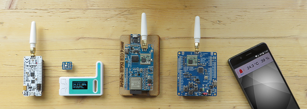
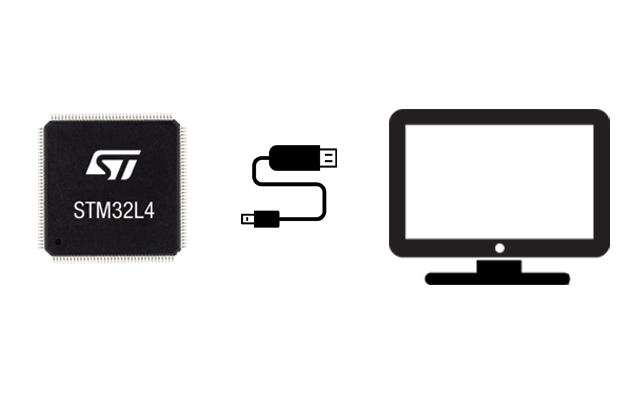
“RadioShuttle STM32 Utility” is a special utility which easily allows uploading and downloading software to/from RadioShuttle STM32-compatible boards, via USB using the DFU protocol. The utility can be used either from a command line from Mac, Windows, and Linux, or in a GUI from Mac and Windows computers. Software can be uploaded to/downloaded from STM32 MCUs. It has been designed to be used with RadioShuttle compatible boards which obtained a valid license (code) during the manufacturing process.
2. System requirements
- Windows:
Windows 7 or higher - Mac:
macOS 10.9 or higher - Linux:
Linux kernel 2.6.16 or higher
glibc 2.4 or higher
Note:
The “RadioShuttle STM32 Utility” software only works with boards activated by the manufacturer. All LoRa boards are prepared for the “STM32 Utility” software.
3. Flash RadioShuttle software to STM32 board
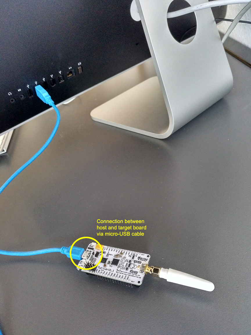
- Connect the board to the computer via a Micro-USB cable (Fig.1).
Important note for Windows users:
Before you can use the STM32 board (target) on Windows, some additional steps must be taken to install the RadioShuttle drivers. See section 7. Install drivers on Windows for instructions.
- Download the RadioShuttle STM32 Tools archive
- Extract the archive
- Open the “RadioShuttle STM32 Utility” tool
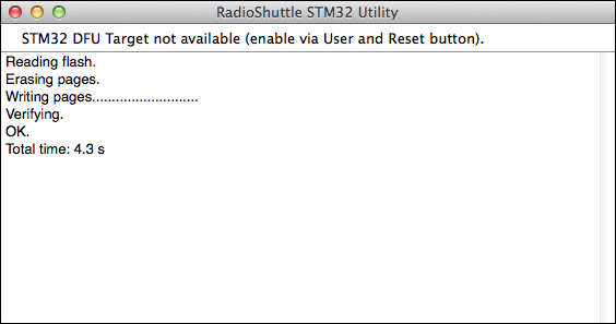
First, the board must be brought into DFU boot mode (status line reads"STM32 DFU Target not available (enable via User and Reset button)"):
- Hold down the “User” button and press the “Reset” button once (Fig. 2)
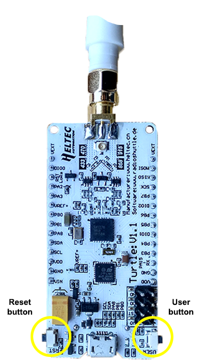
Now the board is switched to USB DFU boot mode.
GUI (Windows/Mac)
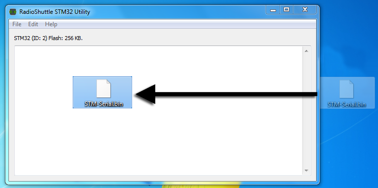
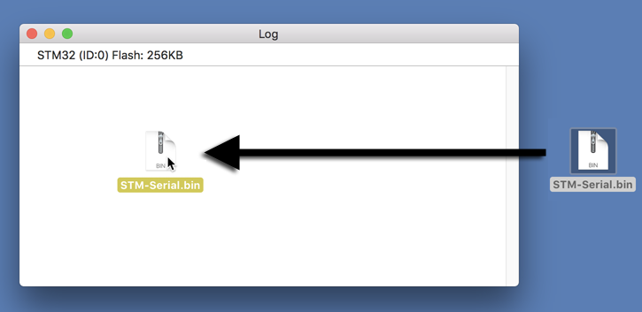
- Drag the “.bin” file containing the software into the window (Fig. 3a+b):
- Or, drag the “.bin” file directly onto the “RadioShuttle STM32 Utility” app icon
- Alternatively, go to “File > Upload to target” and select “.bin”
Command line (Windows/Mac/UNIX)
- See section 6. Command-line parameters
Before uploading new software, the status message must say
"STM32 (ID:0) Flash: 256 kB".
ID: 0 is the enumeration number of the board connected via USB. The utility supports connecting multiple boards to the same host, in this case the ID differentiates between the different boards.
Note that after flashing the software (Fig. 4), the “RadioShuttle STM32 Utility” app verifies the writing content automatically. After successfully flashing the target board an automatic software reset is issued, which means that the board exits the DFU boot mode and starts with the newly flashed program. To bring it again into DFU boot mode, the button combination given at the beginning of this section must be pressed.
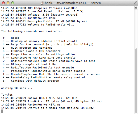
After the software has been successfully flashed, a macOS “Terminal” program window is automatically opened (Fig. 5a) showing any output of the flashed program, e.g. ARM compiler version, voltage and type of source, available memory, etc.
Note:
If “Terminal” does not start automatically (as described above), please open the menu entry “Terminal > ttyusbmodem<…>” in the “RadioShuttle STM32 Utility”.
Within 10 seconds, additional commands can be entered. After this time span the input is disabled.
Available commands:
r -- Reset
d -- Hexdump of memory address [offset count]
h -- help for the command (e.g.: h b [help for blinky])
q -- quit program and continue
B -- CPUBench example CPU benchmark
p -- Properties non volatile settings editor
l -- LoRaPingPong raw LoRa ping pong example
w -- RadioContinuousTX LoRa radio continues wave TX test
b -- Blinky example without LoRa
n -- RadioTestNew RadioShuttle test example
x -- PanicButton RadioShuttle panic button example
t -- RemoteTempSensor RadioShuttle remote temperature sensor
k -- RemoteRelay RadioShuttle remote relay control
c -- Continue with default program
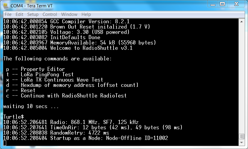
After 10 seconds, the SMT32 Utility displays the used radio frequency, spreading factor, bandwith, the mode the node is started as (e.g. “Node Offline”), etc.
On Windows, the Tera Term program can be used to connect to the correct virtual COM port (Fig. 5b).
- Open “Setup > Serial port…” to specify the correct serial port (in our example below it is “COM4”):
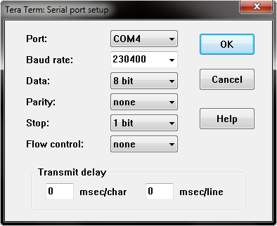
- Click the “OK” button
Tera Term then opens a program window (Fig. 5b) showing any output of the flashed program.
4. Custom settings
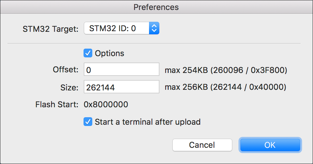
The “Preferences” menu (Fig. 6) is optional and is usually not needed, unless special parameters like a flash start address (offset) differs from the default address, or the flash size should be limited.
- (Windows): Open “Help > Preferences…”
(Mac): Open “RadioShuttle STM32 Utility > Preferences…” - From the “STM32 Target:” pop-up menu select the desired board, e.g. “STM32 ID:0”
- If required, adjust memory offset and size:
Activate the “Options” checkbox and enter the memory offset, to define a custom address, and size. Note that the entries can be specified either in decimal or hexadecimal notation
Custom settings are saved and will be re-used next time the utility starts. The board ID (in case of multiple connected targets) will not be saved. The tool will automatically use the first target board found when it starts.
5. Read out flash memory
- Go to “File > Download from target”
Please note that when using the flash download, the entire target flash memory is extracted and saved into a “.bin” file on the host, even if only a little portion is used – the complete flash content is extracted and saved. This is because during download the utility does not know how much is being used, therefore it reads out everything. To limit the download size, the size options can be set in the preferences.
Important note:
The flash utility will not erase the entire flash chip content, it only erases and flashes the “.bin” file size into the flash and preserves the remaining existing data in the flash.
6. Command-line parameters
Instead of using the “RadioShuttle STM32 Utility”, the RadioShuttle software can also be flashed to the board using the command line tool.
- In the command line, change to the directory in which “RadioShuttleSTM32Tool” is installed
- Enter the following line:
RadioShuttleSTM32Tool
After starting, a list of all available command line options is displayed
Options
-l  list connected STM32 USB-targets
-u  upload image to target device
-d  download image from target device
-e  erase flash chip or pages (via offset/length)
-o  offset of target flash address for download/upload (optional)
-s  size of target flash operation for download/upload/erase
-i  index for multiple targets (default: 0)
-f  image file (default: image.bin)
-q  no text output (quiet)
Attention:
Use the erase flash chip or pages option with caution. When deleting the entire chip, bootloader files and non-volatile memory content may also be removed! As a precaution this option is therefore not available in “RadioShuttle STM32 Utility”.
Examples
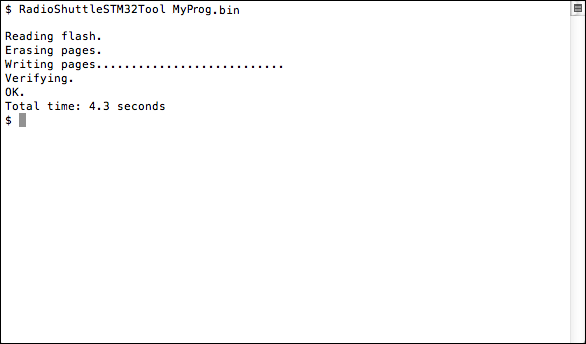
Example for flashing the board with the file “MyProg.bin”:RadioShuttleSTM32Tool MyProg.bin
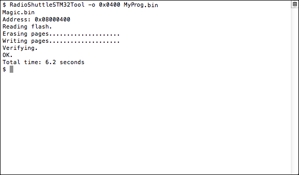
Flashing the board with the “MyProg.bin” file using the flash memory offset 0x0400:RadioShuttleSTM32Tool -o 0x0400 MyProg.bin
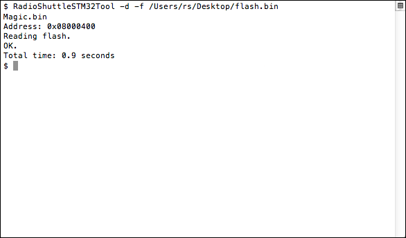
Flash the complete RadioShuttle software of a board into the file “flash.bin”:RadioShuttleSTM32Tool -d -f /Users/rs/Desktop/flash.bin
Exit codes
0: Success
1: No Device
2: Device Read Error
3: Device Write Error
4: Device Erase Error
5: Firmware Verify Error
6: USB Error
7: Parameter Error (command line arguments)
8: Unix Error (out of memory etc)
9: Offset Alignment Error
10: Invalid Start Address
11: Read File Error
12: Write File Error
13: Firmware Too Big
7. Install drivers on Windows
Before you can use the STM32 board (target) on Windows, additional steps must be taken to install the required device drivers.
“STM32 BOOTLOADER” driver installation
- Bring the STM32 board, which you have connected to the Windows computer, into DFU boot mode by holding down the “User” button and pressing the “Reset” button once (Fig. 2)
- Open the Windows “Device Manager”
Note:
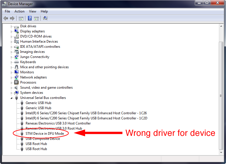
If an older driver was already assigned to the board, or the Windows system has automatically assigned a driver to the STM32 board, e.g. in “Universal Serial Bus devices” or in “Universal Serial Bus controllers”, this must be deleted first:
- Double-click the device entry to open its properties
- In the “Driver” tab click on “Uninstall”
- Make sure that you check the “Delete the driver software for this device” checkbox and confirm with “OK”
- Hold down the “User” button and press the “Reset” button once to bring the board into DFU boot mode again
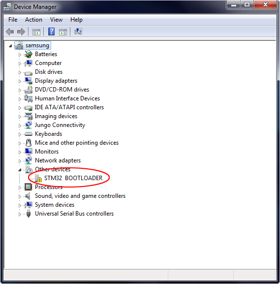
Now the “STM32 BOOTLOADER” entry appears under “Other devices”. Its icon is labelled with a warning that no matching driver could be found by the Windows system:
Now the new driver can be installed:
- Unpack the “RadioShuttle STM32 Tools.zip” archive
- Double-click the “STM32 BOOTLOADER” entry to open its properties
- In the “General” tab click on “Update Driver…”
The Windows system will ask you how you would like to search for the required driver:
- Click on “Browse my computer for driver software”.
(Do not select “Search automatically for updated driver software”!) - Using the “Browse…” button navigate to the unpacked “RadioShuttle STM32 Tools” folder
- In the folder, navigate to “Windows > driver” and click “OK”
- Click on “Next” and confirm the following dialog with “Install”
After Windows has successfully installed the driver software, the entry “STM32 BOOTLOADER” appears in the “Device Manager” window under “Universal Serial Bus devices”:
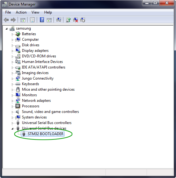
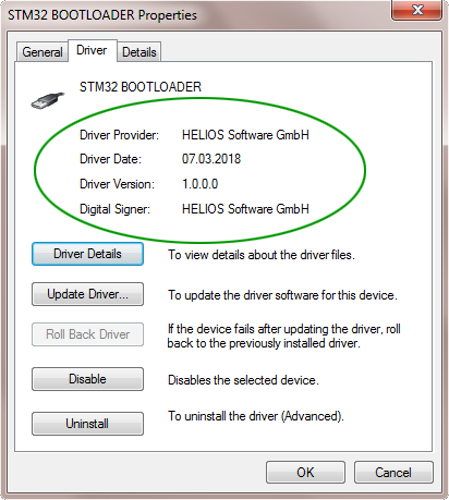
- Double-click on the “STM32 BOOTLOADER” entry and make sure that it looks like this:
CDC DEVICE (Virtual Serial COM Port) installation
In a second step, the “CDC DEVICE” driver needs to be installed:
- Press the “Reset” button on the target board
Note:
If an older driver was already assigned to the board, or the Windows system has automatically assigned a driver to the STM32 board, e.g. in “Ports (COM & LPT)”, this must be deleted first:
- Double-click the device entry to open its properties
- In the “Driver” tab click on “Uninstall”
- Make sure that you check the “Delete the driver software for this device” checkbox and confirm with “OK”
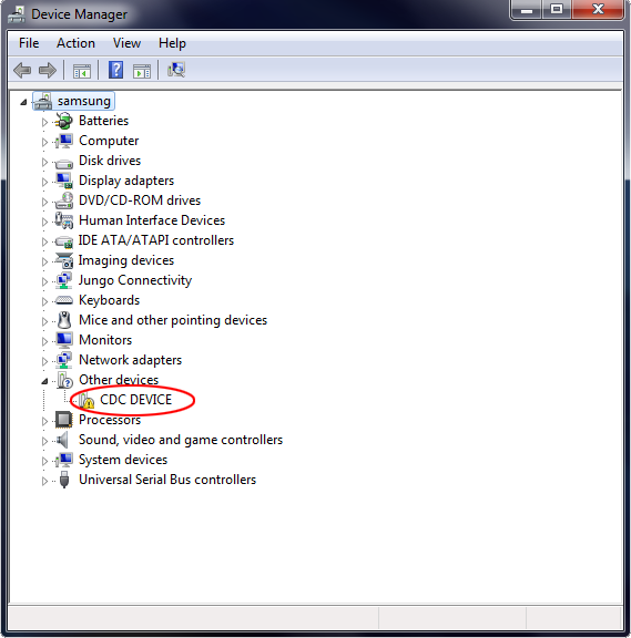
If no existing or older driver had been assigned before, the “CDC DEVICE” entry appears under “Other devices”. Its icon is labelled with a warning that no matching driver could be found by the Windows system:
Now the new driver can be installed:
- Double-click the “CDC DEVICE” entry to open its properties
- In the “General” tab click on “Update Driver…”
The Windows system will ask you how you would like to search for the required driver:
- Click on “Browse my computer for driver software”
(Do not select “Search automatically for updated driver software”!) - Using the “Browse…” button navigate to the unpacked “RadioShuttle STM32 Tools” folder
- In the folder, navigate to “Windows > driver” and click “OK”
- Click on “Next” and confirm the following dialog with “Install”
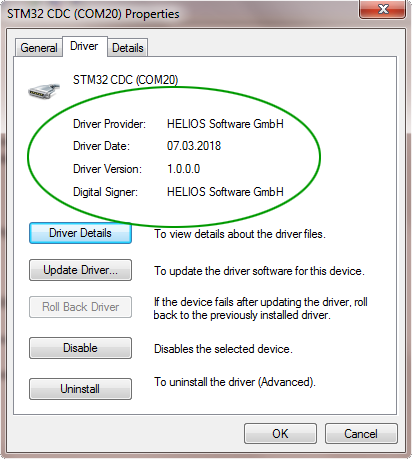
After Windows has successfully installed the driver software, the entry “STM32 CDC (e.g. COM20)” appears in the “Device Manager” window under “Ports (COM & LPT)”:
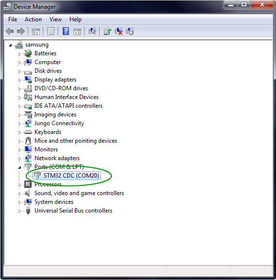
- Double-click on the “STM32 CDC (e.g. COM20)” entry and make sure that it looks like this:
If no existing or older driver had been assigned before, the drivers have been successfully installed, and you can continue in section 3. Flash software to STM32 target board.
8. Licensing
The tool is made available only to customers who obtained a RadioShuttle compatible board which includes a RadioShuttle license. The board must be RadioShuttle enabled at manufacturing otherwise it is not supported and will not work.
9. Q & A
a) My Board does not show up in the “RadioShuttle STM32 Utility”.
Check the following:
- Is the USB cable connected to the host?
- Is the USB cable connected to the board?
- Has the board been switched into DFU boot mode (see 3. Flash software to STM32 board)?
- Is the board supported by RadioShuttle?
b) Flashing fails at address, e.g. 0x08001000.
Some MCU chips may have been write protected, the flash cannot be overwritten or special flash blocks are write-protected.
c) Flash content download fails.
Some MCU chips may have been readout-protected. Please contact your vendor.
d) After flashing, the program does not start.
By default, the start address is 0x08000000. Maybe the software requires another start address which can be specified in the “Preferences” setup. Another option may be that the software (“.bin”) is not compatible with your board or contains software errors. In this case simplify the application and test again.
e) How long does it take to upload and program the flash memory?
It depends on the flash (“.bin”) image size. A small image can be flashed within a second. A larger 200 kB image requires 3 seconds.
© 2018 www.radioshuttle.de